Individual Project (iP):
Team Project (tP):
Week 7 [Sep 30] - Topics
- [W7.1] Requirements: Use Cases
- [W7.2] Design Principles: Basics
- [W7.2a] Design → Introduction → What
Abstraction
- [W7.2b] Design → Design Fundamentals → Abstraction → What
Coupling
-
[W7.2c] Design → Design Fundamentals → Coupling → What
-
[W7.2d] Design → Design Fundamentals → Coupling → How
-
[W7.2e] Design → Design Fundamentals → Coupling → Types of Coupling
Cohesion
- [W7.3] Basic Design Approaches
- [W7.4] IDEs: Intermediate Features
- [W7.4a] Tools → Intellij IDEA → Productivity Shortcuts
- [W7.5] Integration Approaches
- [W7.6] Project Mgt: Scheduling and Tracking
-
[W7.6a] Project Management → Project Planning → Milestones
-
[W7.6b] Project Management → Project Planning → Buffers
-
[W7.6c] Project Management → Project Planning → Issue Trackers
-
[W7.6d] Project Management → Project Planning → Work Breakdown Structure
-
[W7.6e] Project Management → Project Planning → GANTT Charts
-
[W7.6f] Project Management → Project Planning → PERT Charts
-
[W7.6g] Project Management → Teamwork → Team Structures
- [W7.7] Project Mgt: Workflows
-
[W7.7a] Project Management → Revision Control → Forking Flow
-
[W7.7b] Tools → Git and GitHub → Forking Workflow
-
[W7.7c] Project Management → Revision Control → DRCS vs CRCS
-
[W7.7d] Project Management → Revision Control → Feature Branch Flow
-
[W7.7e] Project Management → Revision Control → Centralized Flow
Requirements → Specifying Requirements → Use Cases → Introduction
Can explain use cases
Use Case: A description of a set of sequences of actions, including variants, that a system performs to yield an observable result of value to an
Actor: An actor (in a use case) is a role played by a user. An actor can be a human or another system. Actors are not part of the system; they reside outside the system.
A use case describes an interaction between the user and the system for a specific functionality of the system.
- System:
ATM - Actor: Customer
- Use Case: Check account balance
- User inserts an ATM card
- ATM prompts for PIN
- User enters PIN
- ATM prompts for withdrawal amount
- User enters the amount
- ATM ejects the ATM card and issues cash
- User collects the card and the cash.
- System: A Learning Management System (LMS)
- Actor: Student
- Use Case: Upload file
- Student requests to upload file
- LMS requests for the file location
- Student specifies the file location
- LMS uploads the file
Unified Modeling Language (UML) is a graphical notation to describe various aspects of a software system. UML is the brainchild of three software modeling specialists James Rumbaugh, Grady Booch and Ivar Jacobson (also known as the Three Amigos). Each of them has developed their own notation for modeling software systems before joining force to create a unified modeling language (hence, the term ‘Unified’ in UML). UML is currently the de facto modeling notation used in the software industry.
Use cases capture the functional requirements of a system.
Requirements → Specifying Requirements → Use Cases → Identifying
Can use use cases to list functional requirements of a simple system
A use case is an interaction between a system and its actors.
Actors in Use Cases
Actor: An actor (in a use case) is a role played by a user. An actor can be a human or another system. Actors are not part of the system; they reside outside the system.
Some example actors for a Learning Management System
- Actors: Guest, Student, Staff, Admin,
ExamSys ,LibSys .
A use case can involve multiple actors.
- Software System: LearnSys
- Use case: UC01 conduct survey
- Actors: Staff, Student
An actor can be involved in many use cases.
- Software System: LearnSys
- Actor: Staff
- Use cases: UC01 conduct survey, UC02 Set Up Course Schedule, UC03 Email Class, ...
A single person/system can play many roles.
- Software System: LearnSys
- Person: a student
- Actors (or Roles): Student, Guest, Tutor
Many persons/systems can play a single role.
- Software System: LearnSys
- Actor(or role) : Student
- Persons that can play this role : undergraduate student, graduate student, a staff member doing a part-time course, exchange student
Use cases can be specified at various levels of detail.
Consider the three use cases given below. Clearly, (a) is at a higher level than (b) and (b) is at a higher level than (c).
- System: LearnSys
- Use cases:
a. Conduct a survey
b. Take the survey
c. Answer survey question
While modeling user-system interactions,
- Start with high level use cases and progressively work toward lower level use cases.
- Be mindful at which level of details you are working on and not to mix use cases of different levels.
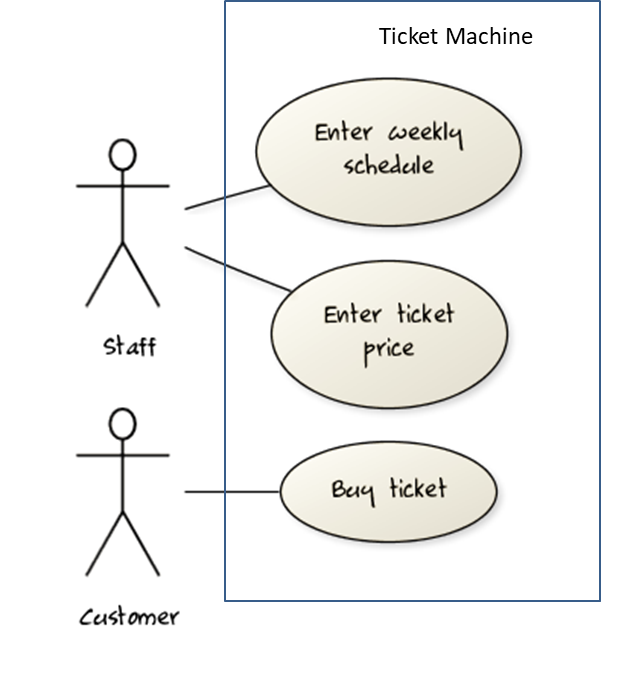
Consider a simple movie ticket vending machine application. Every week, the theatre staff will enter the weekly schedule as well as ticket price for each show. A customer sees the schedule and the ticket price displayed at the machine. There is a slot to insert money, a keypad to enter a code for a movie, a code for the show time, and the number of tickets. A display shows the customer's balance inside the machine. A customer may choose to cancel a transaction before pressing the “buy” button. Printed tickets can be collected from a slot at the bottom of the machine. The machine also displays messages such as "Please enter more money”, “Request fewer tickets" or "SOLD OUT!”. Finally, a "Return Change" button allows the customer to get back his unspent money.
Draw a use case diagram for the above requirements.

Note that most of the details in the description are better given as part of the use case description rather than as low-level use cases in the diagram.
A software house wishes to automate its Quality Assurance division.
The system is to be used by Testers, Programmers and System Administrators. Only an administrator can create new users and assign tasks to programmers. Any tester can create a bug report, as well as set the status of a bug report as ‘closed’. Only a programmer can set the state of a bug report to ‘fixed’, but a programmer cannot set the status of a bug report to ‘closed’. Each tester is assigned just one task at a time. A task involves testing of a particular component for a particular customer. Tester must document the bugs they find. Each bug is given a unique identifier. Other information recorded about the bug is component id, severity, date and time reported, programmer who is assigned to fix it, date fixed, date retested and date closed. The system keeps track of which bugs are assigned to which programmer at any given time. It should be able to generate reports on the number of bugs found, fixed and closed e.g. number of bugs per component and per customer; number of bugs found by a particular tester ; number of bugs awaiting to be fixed; number of bugs awaiting to be retested; number of bugs awaiting to be assigned to programmers etc.
Develop a use case diagram to capture their requirements given below.
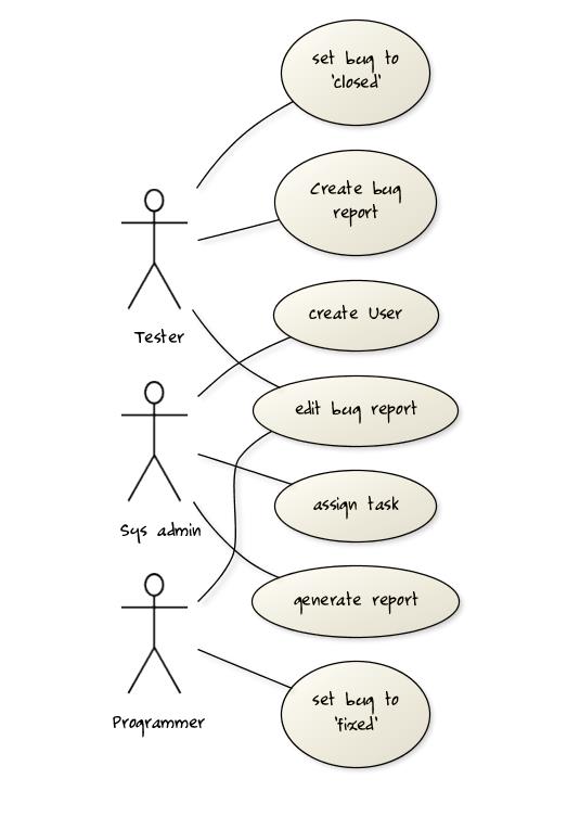
Explanation: The given description contains information not relevant to use case modeling. Furthermore, the description is not enough to complete the use case diagram All these are realities of real projects. However, the process of trying to create this use case diagram prompts us to investigate issues such as:
- Is ‘edit bug report’ a use case or editing the bug report is covered by other use cases such as those for setting the status of bug reports? If it is indeed a separate use case, who are the actors of that use case?
- Does ‘assign task’ simply means ‘assign bug report’ or is there any other type of tasks?
- There was some mention about Customers and Components. Does the system have to support use cases for creating and maintaining details about those entities? For example, should we have a ‘create customer record’ use case?
- Which actors can perform the ‘generate report’ use case? Are reports generated automatically by the system at a specific time or generated ‘on demand’ when users request to view them? Do we have to treat different types of reports as different use cases (in case some types of reports are restricted to some types of users)? The above diagram assumes (just for illustration) that the report is generated on demand and only the system admin can generate any report.
Requirements → Specifying Requirements → Use Cases → Details
Can specify details of a use case in a structured format
Writing use case steps
The main body of the use case is the sequence of steps that describes the interaction between the system and the actors. Each step is given as a simple statement describing who does what.
An example of the main body of a use case.
- Student requests to upload file
- LMS requests for the file location
- Student specifies the file location
- LMS uploads the file
A use case describes only the externally visible behavior, not internal details, of a system i.e. should minimize details that are not part of the interaction between the user and the system.
This example use case step refers to behaviors not externally visible.
- LMS saves the file into the cache and indicates success.
A step gives the intention of the actor (not the mechanics). That means UI details are usually omitted. The idea is to leave as much flexibility to the UI designer as possible. That is, the use case specification should be as general as possible (less specific) about the UI.
The first example below is not a good use case step because contains UI-specific details. The second one is better because it omits UI-specific details.
Bad : User right-clicks the text box and chooses ‘clear’
Good : User clears the input
A use case description can show loops too.
An example of how you can show a loop:
Software System: Square game
Use case:
Actors: Player (multiple players)
- A Player starts the game.
- SquareGame asks for player names.
- Each Player enters his own name.
- SquareGame shows the order of play.
- SquareGame prompts for the current Player to throw die.
- Current Player adjusts the throw speed.
- Current Player triggers the die throw.
- Square Game shows the face value of the die.
- Square Game moves the Player's piece accordingly.
Steps 5-9 are repeated for each Player, and for as many rounds as required until a Player reaches the 100th square. - Square Game shows the Winner.
Use case ends.
The Main Success Scenario (MSS) describes the most straightforward interaction for a given use case, which assumes that nothing goes wrong. This is also called the Basic Course of Action or the Main Flow of Events of a use case.
Note how the MSS in the example below assumes that all entered details are correct and ignores problems such as timeouts, network outages etc. For example, MSS does not tell us what happens if the user enters an incorrect data.
System: Online Banking System (OBS)
Use case: UC23 - Transfer Money
Actor: User MSS:
- User chooses to transfer money.
- OBS requests for details of the transfer.
- User enters the requested details.
- OBS requests for confirmation.
- OBS transfers the money and displays the new account balance.
Use case ends.
Extensions are "add-on"s to the MSS that describe exceptional/alternative flow of events. They describe variations of the scenario that can happen if certain things are not as expected by the MSS. Extensions appear below the MSS.
This example adds some extensions to the use case in the previous example.
- System: Online Banking System (OBS)
- Use case: UC23 - Transfer Money
- Actor: User
- MSS:
- User chooses to transfer money.
- OBS requests for details of the transfer.
- User enters the requested details.
- OBS requests for confirmation.
- OBS transfers the money and displays the new account balance.
- Use case ends.
- Extensions:
- 3a. OBS detects an error in the entered data.
- 3a1. OBS requests for the correct data.
- 3a2. User enters new data.
- Steps 3a1-3a2 are repeated until the data entered are correct.
- Use case resumes from step 4.
- 3b. User requests to effect the transfer in a future date.
- 3b1. OBS requests for confirmation.
- 3b2. User confirms future transfer.
- Use case ends.
- *a. At any time, User chooses to cancel the transfer.
- *a1. OBS requests to confirm the cancellation.
- *a2. User confirms the cancellation.
- Use case ends.
- *b. At any time, 120 seconds lapse without any input from the User.
- *b1. OBS cancels the transfer.
- *b2. OBS informs the User of the cancellation.
- Use case ends.
- 3a. OBS detects an error in the entered data.
Note that the numbering style is not a universal rule but a widely used convention. Based on that convention,
- either of the extensions marked
3a.and3b.can happen just after step3of the MSS. - the extension marked as
*a.can happen at any step (hence, the*).
When separating extensions from the MSS, keep in mind that the MSS should be self-contained. That is, the MSS should give us a complete usage scenario.
Also note that it is not useful to mention events such as power failures or system crashes as extensions because the system cannot function beyond such catastrophic failures.
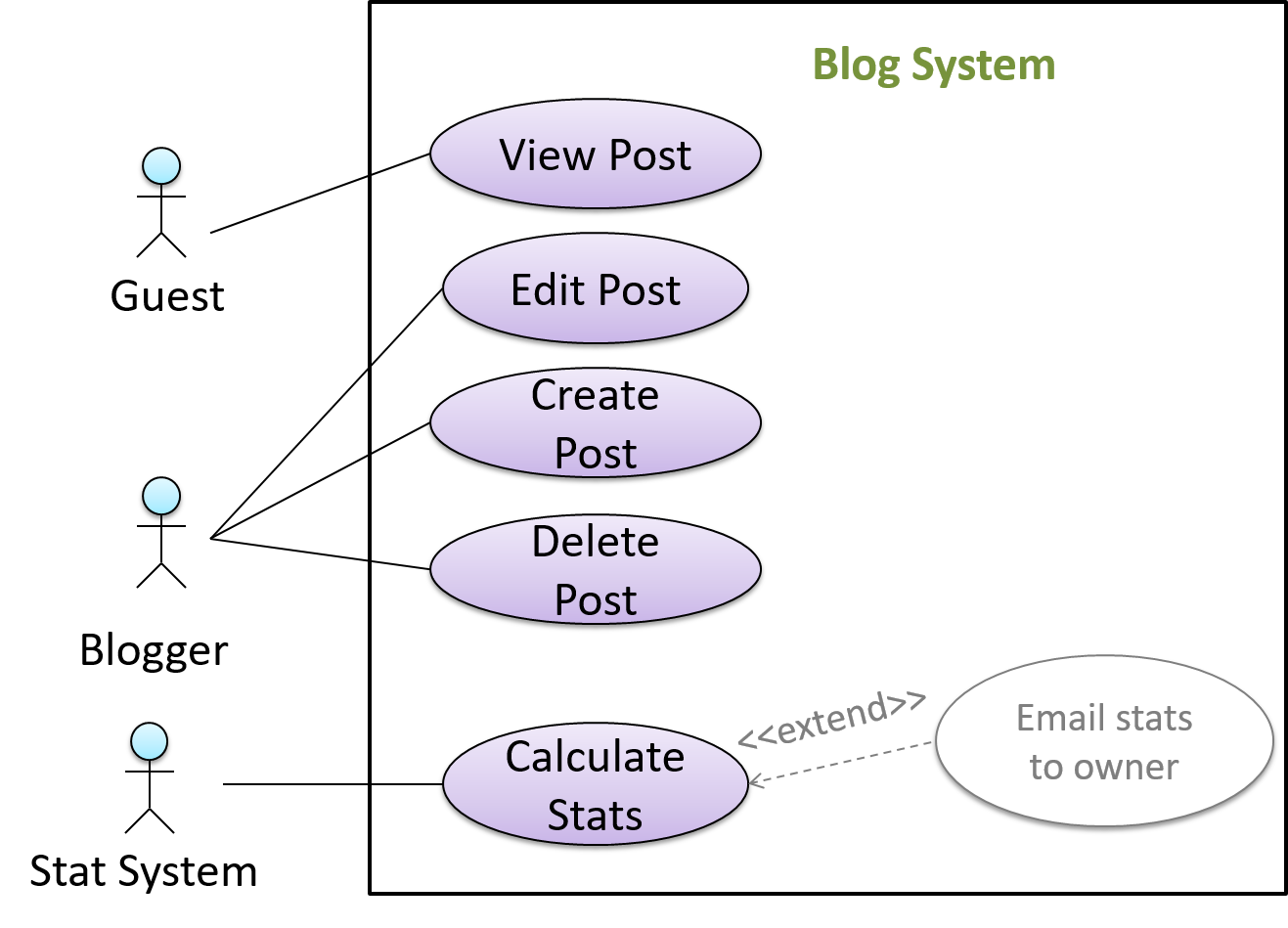
In use case diagrams you can use the <<extend>> arrows to show extensions. Note the direction of the arrow is from the extension to the use case it extends and the arrow uses a dashed line.
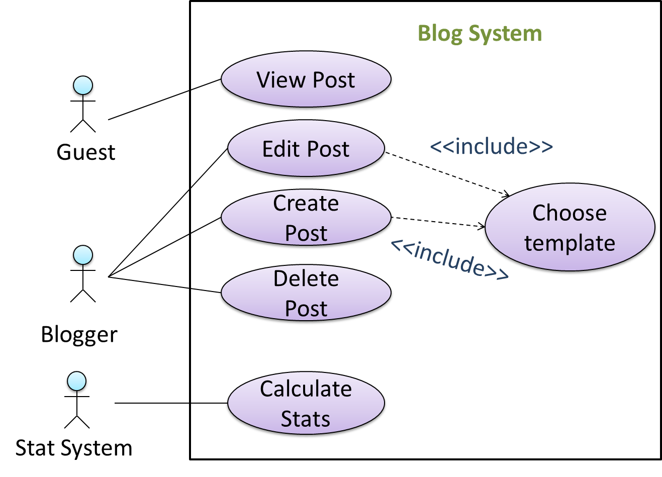
A use case can include another use case. Underlined text is commonly used to show an inclusion of a use case.
This use case includes two other use cases, one in step 1 and one in step 2.
- Software System: LearnSys
- Use case: UC01 - Conduct Survey
- Actors: Staff, Student
- MSS:
- Staff creates the survey (UC44).
- Student completes the survey (UC50).
- Staff views the survey results.
Use case ends.
Inclusions are useful,
- when you don't want to clutter a use case with too many low-level steps.
- when a set of steps is repeated in multiple use cases.
We use a dotted arrow and a <<include>> annotation to show use case inclusions in a use case diagram. Note how the arrow direction is different from the <<extend>> arrows.
Preconditions specify the specific state we expect the system to be in before the use case starts.
Software System: Online Banking System
Use case: UC23 - Transfer Money
Actor: User
Preconditions: User is logged in
MSS:
- User chooses to transfer money.
- OBS requests for details for the transfer.
...
Guarantees specify what the use case promises to give us at the end of its operation.
Software System: Online Banking System
Use case: UC23 - Transfer Money
Actor: User
Preconditions: User is logged in.
Guarantees:
- Money will be deducted from the source account only if the transfer to the destination account is successful
- The transfer will not result in the account balance going below the minimum balance required.
MSS:
- User chooses to transfer money.
- OBS requests for details for the transfer.
...
Complete the following use case (MSS, extensions, etc.). Note that you should not blindly follow how the existing
- System: EZ-Link machine
- Use case: UC2 top-up EZ-Link card
- Actor: EZ-Link card user
- System: EZ-Link machine (those found at MRTs)
- Use case: UC2 top-up EZ-Link card
- Actor: EZ-Link card user
- Preconditions: All hardware in working order.
- Guarantees: MSS → the card will be topped-up.
- MSS:
- User places the card on the reader.
- System displays card details and prompts for desired action.
- User selects top-up.
- System requests for top-up details (amount, payment option, receipt required?).
- User enters details.
- System processes cash payment (UC02) or NETS payment (UC03).
- System updates the card value.
- System indicates transaction as completed.
- If requested in step 5, system prints receipt.
- User removes the card.
- Use case ends.
- Extensions:
- *a. User removed card or other hardware error detected.
- *a1. System indicates the transaction has been aborted.
- Use case ends.
- *a. User removed card or other hardware error detected.
Notes:
- We assume that the only way to cancel a transaction is by removing the card.
- By not breaking step 4 into further steps, we avoid committing to a particular mechanism to enter data. For example, we are free to accept all data in one screen.
- In step 5, we assume that the input mechanism does not allow any incorrect data.
- System: EZ-Link machine
- Use case: UC03 process NETS payment
- Actor: EZ-Link card user
- Preconditions: A transaction requiring payment is underway.
- Guarantees: MSS → Transaction amount is transferred from user account to EZ-Link company account.
- MSS:
- System requests to insert ATM card.
- User inserts the ATM card.
- System requests for PIN.
- User enters PIN.
- System reports success.
- Use case ends.
- Extensions:
- 2a. Unacceptable ATM card (damaged or inserted wrong side up).
- ...
- 4a. Wrong PIN.
- ...
- 4b. Insufficient funds.
- ...
- *a. Connection to the NETS gateway is disrupted.
- ...
- 2a. Unacceptable ATM card (damaged or inserted wrong side up).
Note: UC02 can be written along similar lines.
Complete the following use case (MSS, extensions, etc.).
- System: LearnSys (an online Learning Management System)
- Use case: UC01 reply to post in the forum
- Actor: Student
- System: LearnSys
- Use case: UC01 reply to post in the forum
- Actor: Student
- Preconditions: Student is logged in and has permission to post in the forum. The post to which the Student replies already exists.
- MSS:
- Student chooses to reply to an existing post.
- LearnSys requests the user to enter post details.
- Student enters post details.
- Student submits the post.
- LearnSys displays the post.
- Use case ends.
- Extensions:
- *a. Internet connection goes down.
- ...
- *b. LearnSys times out
- ...
- 3a. Student chooses to ‘preview’ the post.
- 3a1. LearnSys shows a preview.
- 3a2. User chooses to go back to editing.
- Use case resumes at step 3.
- 3b. Student chooses to attach picture/file
- ...
- 3c. Student chooses to save the post as a draft.
- 3c1. LearnSys confirms draft has been saved.
- Use case ends.
- 3d. Student chooses to abort the operation.
- ...
- 4a. The post being replied to is deleted by the owner while the reply is being entered.
- ...
- 4b. Unacceptable data entered.
- ...
- *a. Internet connection goes down.
Which of these cannot appear as part of a use case description?
- a. Use case identifier
- b. Preconditions
- c. Guarantees
- d. References to another use case
- e. Main Success Scenario
- f. Performance requirements
- g. Extensions
- h. Inclusions
(f)
Explanation: Performance requirements are non-functional requirements. They are not captured in use cases.
Identify problems with this use case description.
- System: EZ-Link machine (those found at MRTs)
- Use case: UC2 top-up EZ-Link card
- Actor: EZ-Link card user
- Preconditions: All hardware in working order.
- Guarantees: If MSS completes at least until step 7, the card will be topped-up.
- MSS:
- User places the card on the reader.
- System displays card details and prompts for desired action.
- User selects top-up.
- System requests for top-up details (amount, payment option, receipt required?).
- User enters details.
- System processes cash payment (UC02) or NETS payment (UC03).
- System updates the card value.
- System indicates transaction as completed.
- If requested in step 5, system prints receipt.
- User removes the card.
- Use case ends.
- Extensions:
- *a. User removed card or other hardware error detected.
- *a1. System indicates the transaction has been aborted.
- Use case ends.
- *a. User removed card or other hardware error detected.
- a. It does not consider ‘system crash’ scenario.
- b. It does not contain enough UI details.
- c. The extension given is in fact an inclusion.
- d. No post conditions are given.
- e. ‘Use case ends’ is duplicated.
None.
Explanation: Catastrophic failures such as ‘system crash’ need not be included in a use case. A use case is not supposed to contain UI details. Post conditions are optional. It is not a problem to have multiple exit points for a use case.
Requirements → Specifying Requirements → Use Cases → Usage
Can optimize the use of use cases
You can use actor generalization in use case diagrams using a symbol similar to that of UML notation for inheritance.
In this example, actor Blogger can do all the use cases the actor Guest can do, as a result of the actor generalization relationship given
in the diagram.
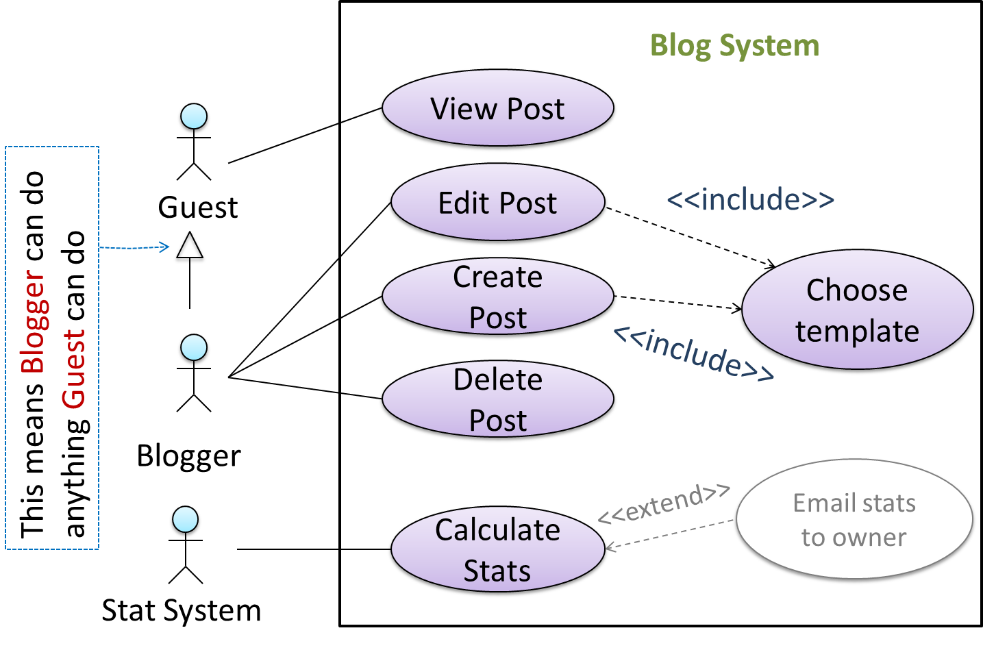
Do not over-complicate use case diagrams by trying to include everything possible. A use case diagram is a brief summary of the use cases that is used as a starting point. Details of the use cases can be given in the use case descriptions.
Some include ‘System’ as an actor to indicate that something is done by the system itself without being initiated by a user or an external system.
The diagram below can be used to indicate that the system generates daily reports at midnight.
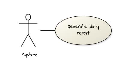
However, others argue that only use cases providing value to an external user/system should be shown in the use case diagram. For example, they argue that ‘view daily report’ should be the use case and generate daily report is not to be shown in the use case diagram because it is simply something the system has to do to support the view daily report use case.
We recommend that you follow the latter view (i.e. not to use System as a user). Limit use cases for modeling behaviors that involve an external actor.
UML is not very specific about the text contents of a use case. Hence, there are many styles for writing use cases. For example, the steps can be written as a continuous paragraph. Use cases should be easy to read. Note that there is no strict rule about writing all details of all steps or a need to use all the elements of a use case.
There are some advantages of documenting system requirements as use cases:
- Because they use a simple notation and plain English descriptions, they are easy for users to understand and give feedback.
- They decouple user intention from mechanism (note that use cases should not include UI-specific details), allowing the system designers more freedom to optimize how a functionality is provided to a user.
- Identifying all possible extensions encourages us to consider all situations that a software product might face during its operation.
- Separating typical scenarios from special cases encourages us to optimize the typical scenarios.
One of the main disadvantages of use cases is that they are not good for capturing requirements that does not involve a user interacting with the system. Hence, they should not be used as the sole means to specify requirements.
What are the advantages of using use cases (the textual form) for requirements modelling?
- a. They can be fairly detailed but still natural enough for users for users to understand and give feedback.
- b. The UI-independent nature of use case specification allows the system designers more freedom to decide how a functionality is provided to a user.
- c. Extensions encourage us to consider all situations a software product might face during its operations.
- d. They encourage us to identify and optimize the typical scenario of usage over exceptional usage scenarios.
(a) (b) (c) (d)
Which of these are correct?
- a. Use case are not very suitable for capturing non-functional requirements.
- b. Use case diagrams are less detailed than textual use cases.
- c. Use cases are better than user stories.
- d. Use cases can be expressed at different levels of abstraction.
(a)(b)(d)
Explanation: It is not correct to say one format is better than the other. It depends on the context.
Design → Introduction → What
Can explain what is software design
Design in the creative process of transforming the problem into a solution; the solution is also called design. -- 📖 Software Engineering Theory and Practice, Shari Lawrence; Atlee, Joanne M. Pfleeger
Software design has two main aspects:
- Product/external design: designing the external behavior of the product to meet the users' requirements. This is usually done by product designers with the input from business analysts, user experience experts, user representatives, etc.
- Implementation/internal design: designing how the product will be implemented to meet the required external behavior. This is usually done by software architects and software engineers.
Abstraction
Design → Design Fundamentals → Abstraction → What
Can explain abstraction
Abstraction is a technique for dealing with complexity. It works by establishing a level of complexity we are interested in, and suppressing the more complex details below that level.
The guiding principle of abstraction is that only details that are relevant to the current perspective or the task at hand needs to be considered. As most programs are written to solve complex problems involving large amounts of intricate details, it is impossible to deal with all these details at the same time. That is where abstraction can help.
Data abstraction: abstracting away the lower level data items and thinking in terms of bigger entities
Within a certain software component, we might deal with a user data type, while ignoring the details contained in the user data item such as name, and date of birth. These details have been ‘abstracted away’ as they do not affect the task of that software component.
Control abstraction: abstracting away details of the actual control flow to focus on tasks at a higher level
print(“Hello”) is an abstraction of the actual output mechanism within the computer.
Abstraction can be applied repeatedly to obtain progressively higher levels of abstractions.
An example of different levels of data abstraction: a File is a data item that is at a higher level than an array and an array is at a higher level than a bit.
An example of different levels of control abstraction: execute(Game) is at a higher level than print(Char) which is at a higher than an Assembly
language instruction MOV.
Abstraction is a general concept that is not limited to just data or control abstractions.
Some more general examples of abstraction:
- An OOP class is an abstraction over related data and behaviors.
- An architecture is a higher-level abstraction of the design of a software.
- Models (e.g., UML models) are abstractions of some aspect of reality.
Coupling
Design → Design Fundamentals → Coupling → What
Can explain coupling
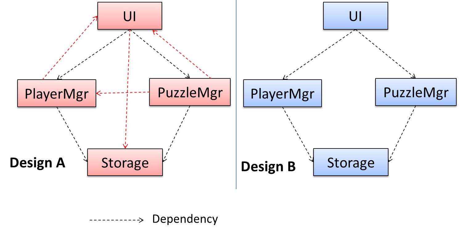
Coupling is a measure of the degree of dependence between components, classes, methods, etc. Low coupling indicates that a component is less dependent on other components. High coupling (aka tight coupling or strong coupling) is discouraged due to the following disadvantages:
- Maintenance is harder because a change in one module could cause changes in other modules coupled to it (i.e. a ripple effect).
- Integration is harder because multiple components coupled with each other have to be integrated at the same time.
- Testing and reuse of the module is harder due to its dependence on other modules.
In the example below, design A appears to have a more coupling between the components than design B.
Discuss the coupling levels of alternative designs x and y.
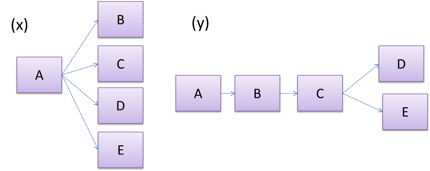
Overall coupling levels in x and y seem to be similar (neither has more dependencies than the other). (Note that the number of dependency links is not a definitive measure of the level of coupling. Some links
may be stronger than the others.). However, in x, A is highly-coupled to the rest of the system while B, C, D, and E are standalone (do not depend on
anything else). In y, no component is as highly-coupled as A of x. However, only D and E are standalone.
Explain the link (if any) between regressions and coupling.
When the system is highly-coupled, the risk of regressions is higher too e.g. when component A is modified, all components ‘coupled’ to component A risk ‘unintended behavioral changes’.
Discuss the relationship between coupling and
Coupling decreases testability because if the
Choose the correct statements.
- a. As coupling increases, testability decreases.
- b. As coupling increases, the risk of regression increases.
- c. As coupling increases, the value of automated regression testing increases.
- d. As coupling increases, integration becomes easier as everything is connected together.
- e. As coupling increases, maintainability decreases.
(a)(b)(c)(d)(e)
Explanation: High coupling means either more components require to be integrated at once in a big-bang fashion (increasing the risk of things going wrong) or more drivers and stubs are required when integrating incrementally.
Design → Design Fundamentals → Coupling → How
Can reduce coupling
X is coupled to Y if a change to Y can potentially require a change in X.
If Foo class calls the method Bar#read(), Foo is coupled to Bar because a change to Bar can potentially
(but not always) require a change in the Foo class e.g. if the signature of the Bar#read() is changed, Foo needs to change as well, but a change to the Bar#write() method may not require a change in the Foo class because Foo does not call Bar#write().
class Foo{
    ...
    new Bar().read();
    ...
}

class Bar{
    void read(){
        ...
    }

    void write(){
        ...
    }
}
Some examples of coupling: A is coupled to B if,
Ahas access to the internal structure ofB(this results in a very high level of coupling)AandBdepend on the same global variableAcallsBAreceives an object ofBas a parameter or a return valueAinherits fromBAandBare required to follow the same data format or communication protocol
Which of these indicate a coupling between components A and B?
- a. component A has access to internal structure of component B.
- b. component A and B are written by the same developer.
- c. component A calls component B.
- d. component A receives an object of component B as a parameter.
- e. component A inherits from component B.
- f. components A and B have to follow the same data format or communication protocol.
(a)(b)(c)(d)(e)(f)
Explanation: Being written by the same developer does not imply a coupling.
Design → Design Fundamentals → Coupling → Types of Coupling
Can identify types of coupling
Some examples of different coupling types:
- Content coupling: one module modifies or relies on the internal workings of another module e.g., accessing local data of another module
- Common/Global coupling: two modules share the same global data
- Control coupling: one module controlling the flow of another, by passing it information on what to do e.g., passing a flag
- Data coupling: one module sharing data with another module e.g. via passing parameters
- External coupling: two modules share an externally imposed convention e.g., data formats, communication protocols, device interfaces.
- Subclass coupling: a class inherits from another class. Note that a child class is coupled to the parent class but not the other way around.
- Temporal coupling: two actions are bundled together just because they happen to occur at the same time e.g. extracting a contiguous block of code as a method although the code block contains statements unrelated to each other
Cohesion
Design → Design Fundamentals → Cohesion → What
Can explain cohesion
Cohesion is a measure of how strongly-related and focused the various responsibilities of a component are. A highly-cohesive component keeps related functionalities together while keeping out all other unrelated things.
Higher cohesion is better. Disadvantages of low cohesion (aka weak cohesion):
- Lowers the understandability of modules as it is difficult to express module functionalities at a higher level.
- Lowers maintainability because a module can be modified due to unrelated causes (reason: the module contains code unrelated to each other) or many many modules may need to be modified to achieve a small change in behavior (reason: because the code realated to that change is not localized to a single module).
- Lowers reusability of modules because they do not represent logical units of functionality.
Design → Design Fundamentals → Cohesion → How
Can increase cohesion
Cohesion can be present in many forms. Some examples:
- Code related to a single concept is kept together, e.g. the
Studentcomponent handles everything related to students. - Code that is invoked close together in time is kept together, e.g. all code related to initializing the system is kept together.
- Code that manipulates the same data structure is kept together, e.g. the
GameArchivecomponent handles everything related to the storage and retrieval of game sessions.
Suppose a Payroll application contains a class that deals with writing data to the database. If the class include some code to show an error dialog to the user if the database is unreachable, that class is not cohesive because it seems to be interacting with the user as well as the database.
Compare the cohesion of the following two versions of the EmailMessage class. Which one is more cohesive and why?
// version-1
class EmailMessage {
    private String sendTo;
 	  private String subject;
    private String message;

    public EmailMessage(String sendTo, String subject, String message) {
        this.sendTo = sendTo;
        this.subject = subject;
        this.message = message;
    }

    public void sendMessage() {
        // sends message using sendTo, subject and message
    }
}

// version-2
class EmailMessage {
    private String sendTo;
    private String subject;
    private String message;
    private String username;

    public EmailMessage(String sendTo, String subject, String message) {
        this.sendTo = sendTo;
        this.subject = subject;
        this.message = message;
    }

    public void sendMessage() {
        // sends message using sendTo, subject and message
    }

    public void login(String username, String password) {
        this.username = username;
        // code to login
    }
}
Version 2 is less cohesive.
Explanation: Version 2 is handling functionality related to login, which is not directly related to the concept of ‘email message’ that the class is supposed to represent. On a related note, we can improve the cohesion of both versions by removing the sendMessage functionality. Although sending message is related to emails, this class is supposed to represent an email message, not an email server.
Design → Design Approaches → Top-Down and Bottom-Up Design
Can explain top-down and bottom-up design
Multi-level design can be done in a top-down manner, bottom-up manner, or as a mix.
- Top-down: Design the high-level design first and flesh out the lower levels later. This is especially useful when designing big and novel systems where the high-level design needs to be stable before lower levels can be designed.
- Bottom-up: Design lower level components first and put them together to create the higher-level systems later. This is not usually scalable for bigger systems. One instance where this approach might work is when designing a variations of an existing system or re-purposing existing components to build a new system.
- Mix: Design the top levels using the top-down approach but switch to a bottom-up approach when designing the bottom levels.
Top-down design is better than bottom-up design.
False
Explanation: Not necessarily. It depends on the situation. Bottom-up design may be preferable when there are lot of existing components we want to reuse.
Design Approaches → Agile Design → Agile Design
Can explain agile design
Agile design can be contrasted with full upfront design in the following way:
Agile designs are emergent, they’re not defined up front. Your overall system design will emerge over time, evolving to fulfill new requirements and take advantage of new technologies as appropriate. Although you will often do some initial architectural modeling at the very beginning of a project, this will be just enough to get your team going. This approach does not produce a fully documented set of models in place before you may begin coding. -- adapted from agilemodeling.com
Agile design camp expects the design to change over the product’s lifetime.
True
Explanation: Yes, that is why they do not believe in spending too much time creating a detailed and full design at the very beginning. However, the architecture is expected to remain relatively stable even in the agile design approach.
Implementation → Integration → Approaches → Late-and-One-Time vs Early-and-Frequent
Can explain how integration approaches vary based on timing and frequency
In terms of timing and frequency, there are two general approaches to integration: late and one-time, early and frequent.
Late and one-time: wait till all components are completed and integrate all finished components near the end of the project.
This approach is not recommended because integration often causes many component incompatibilities (due to previous miscommunications and misunderstandings) to surface which can lead to delivery delays i.e. Late integration → incompatibilities found → major rework required → cannot meet the delivery date.
Early and frequent: integrate early and evolve each part in parallel, in small steps, re-integrating frequently.
A
Here is an animation that compares the two approaches:
Implementation → Integration → Approaches → Big-Bang vs Incremental Integration
Can explain how integration approaches vary based on amount merged at a time
Big-bang integration: integrate all components at the same time.
Big-bang is not recommended because it will uncover too many problems at the same time which could make debugging and bug-fixing more complex than when problems are uncovered incrementally.
Incremental integration: integrate few components at a time. This approach is better than the big-bang integration because it surfaces integration problems in a more manageable way.
Here is an animation that compares the two approaches:
Give two arguments in support and two arguments against the following statement.
Because there is no external client, it is OK to use big bang integration for a school project.
Arguments for:
- It is relatively simple; even big-bang can succeed.
- Project duration is short; there is not enough time to integrate in steps.
- The system is non-critical, non-production (demo only); the cost of integration issues is relatively small.
Arguments against:
- Inexperienced developers; big-bang more likely to fail
- Too many problems may be discovered too late. Submission deadline (fixed) can be missed.
- Team members have not worked together before; increases the probability of integration problems.
Implementation → Integration → Approaches → Top-Down vs Bottom-Up Integration
Can explain how integration approaches vary based on the order of integration
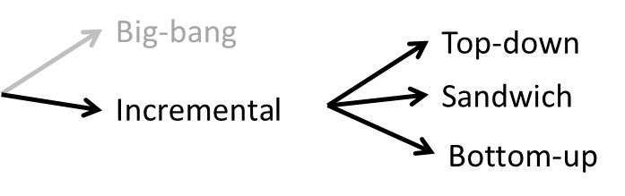
Based on the order in which components are integrated, incremental integration can be done in three ways.
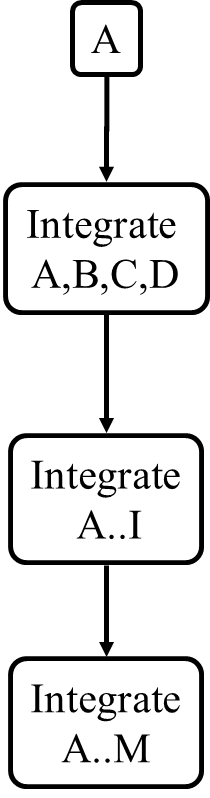
Top-down integration: higher-level components are integrated before bringing in the lower-level components. One advantage of this approach is that higher-level problems can be discovered early. One disadvantage
is that this requires the use of
Stub: A stub has the same interface as the component it replaces, but its implementation is so simple that it is unlikely to have any bugs. It mimics the responses of the component, but only for the a limited set of predetermined inputs. That is, it does not know how to respond to any other inputs. Typically, these mimicked responses are hard-coded in the stub rather than computed or retrieved from elsewhere, e.g. from a database.
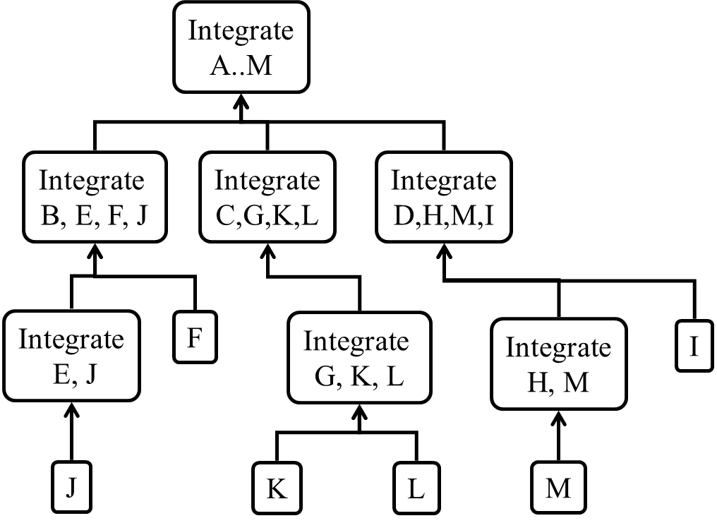
Bottom-up integration: the reverse of top-down integration. Note that when integrating lower level components,
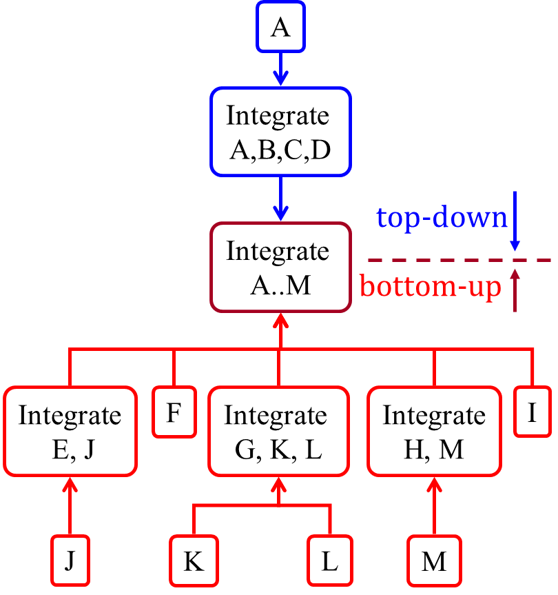
Sandwich integration: a mix of the top-down and the bottom-up approaches. The idea is to do both top-down and bottom-up so as to 'meet' in the middle.
Here is an animation that compares the three approaches:
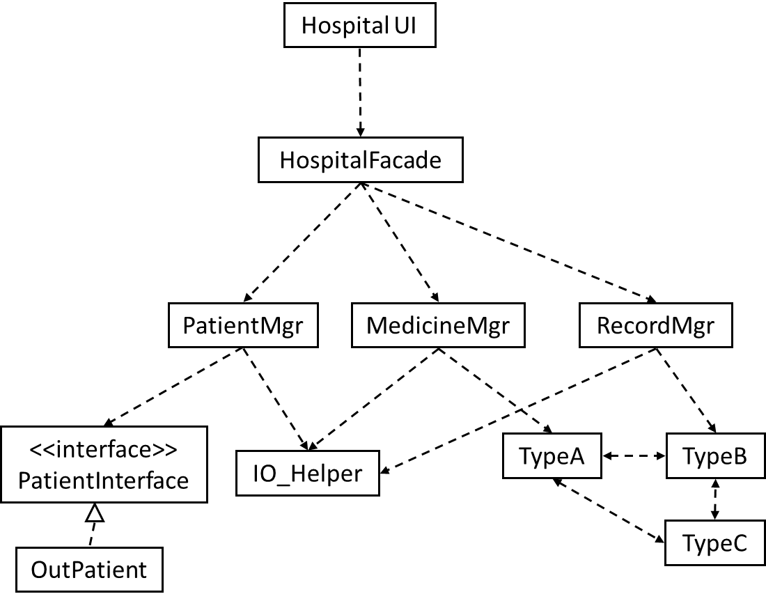
Suggest an integration strategy for the system represented by following diagram. You need not follow a strict top-down, bottom-up, sandwich, or big bang approach. Dashed arrows represent dependencies between classes.
Also take into account the following facts in your test strategy.
HospitalUIwill be developed early, so as to get customer feedback early.HospitalFacadeshields the UI from complexities of the application layer. It simply redirects the method calls received to the appropriate classes belowIO_Helperis to be reused from an earlier project, with minor modifications- Development of
OutPatientcomponent has been outsourced, and the delivery is not expected until the 2nd half of the project.
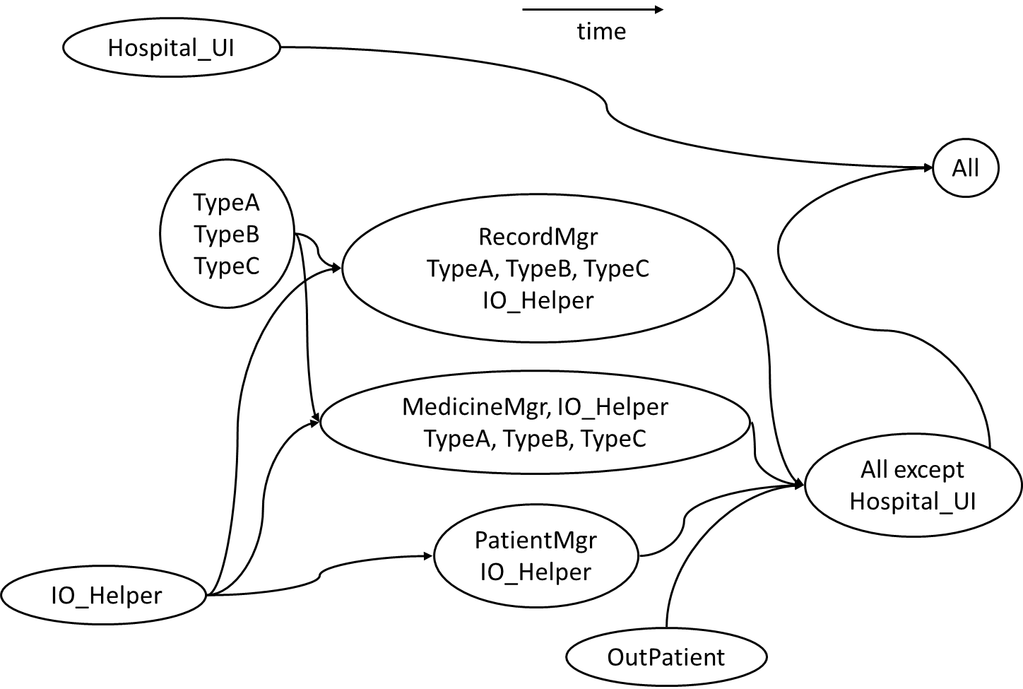
There can be many acceptable answers to this question. But any good strategy should consider at least some of the below.
- Because
HospitalUIwill be developed early, it’s OK to integrate it early, using stubs, rather than wait for the rest of the system to finish. (i.e. a top-down integration is suitable forHospitalUI) - Because
HospitalFacadeis unlikely to have a lot of business logic, it may not be worth to write stubs to test it (i.e. a bottom-up integration is better forHospitalFacade). - Because
IO_Helperis to be reused from an earlier project, we can finish it early. This is especially suitable since there are many classes that use it. ThereforeIO_Helpercan be integrated with the dependent classes in bottom-up fashion. - Because
OutPatientclass may be delayed, we may have to integratePatientMgrusing a stub. TypeA,TypeB, andTypeCseem to be tightly coupled. It may be a good idea to test them together.
Given below is one possible integration test strategy. Relative positioning also indicates a rough timeline.
Consider the architecture given below. Describe the order in which components will be integrated with one another if the following integration strategies were adopted.
a) top-down b) bottom-up c) sandwich
Note that dashed arrows show dependencies (e.g. A depend on B, C, D and therefore, higher-level than B, C and D).
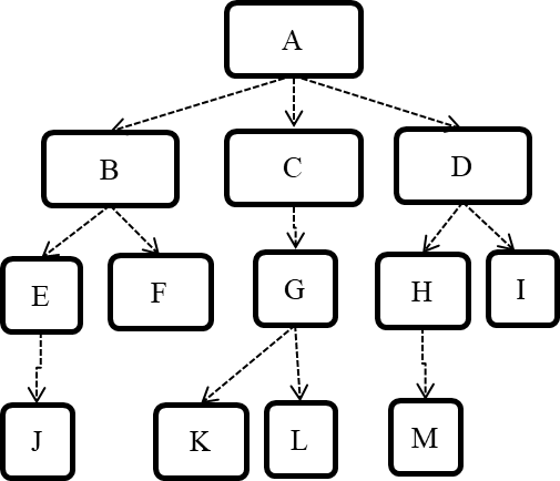
a) Diagram:
b) Diagram:
c) Diagram:
Project Management → Project Planning → Milestones
Can explain milestones
A milestone is the end of a stage which indicates a significant progress. We should take into account dependencies and priorities when deciding on the features to be delivered at a certain milestone.
Each intermediate product release is a milestone.
In some projects, it is not practical to have a very detailed plan for the whole project due to the uncertainty and unavailability of required information. In such cases, we can use a high-level plan for the whole project and a detailed plan for the next few milestones.
Milestones for the Minesweeper project, iteration 1
| Day | Milestones |
|---|---|
| Day 1 | Architecture skeleton completed |
| Day 3 | ‘new game’ feature implemented |
| Day 4 | ‘new game’ feature tested |
Project Management → Project Planning → Buffers
Can explain buffers
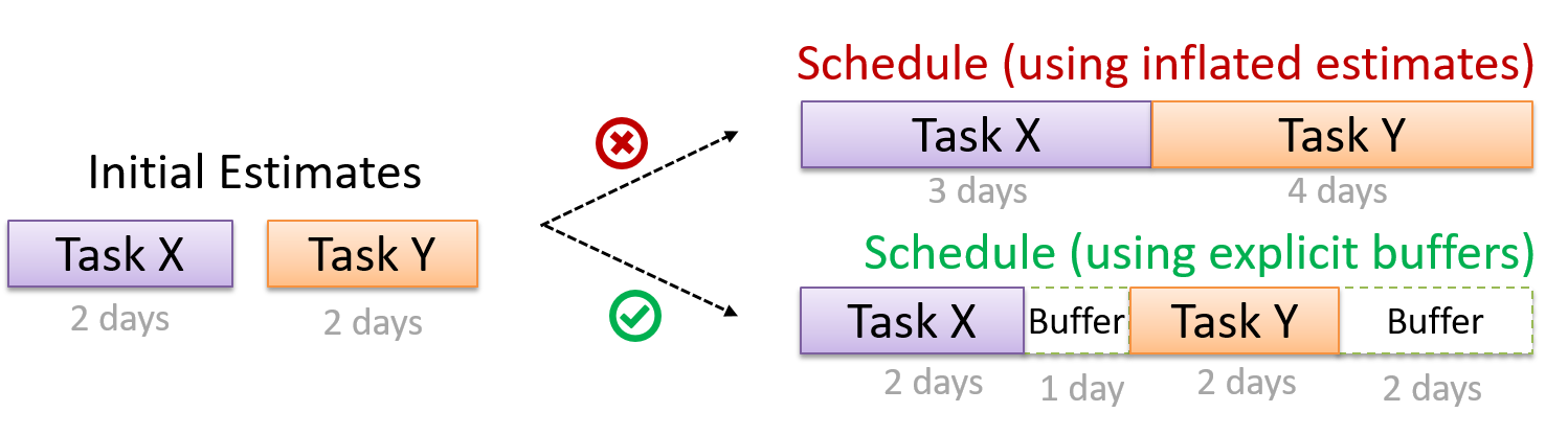
A buffer is a time set aside to absorb any unforeseen delays. It is very important to include buffers in a software project schedule because effort/time estimations for software development is notoriously hard. However, do not inflate task estimates to create hidden buffers; have explicit buffers instead. Reason: With explicit buffers it is easier to detect incorrect effort estimates which can serve as a feedback to improve future effort estimates.
Project Management → Project Planning → Issue Trackers
Can explain issue trackers
Keeping track of project tasks (who is doing what, which tasks are ongoing, which tasks are done etc.) is an essential part of project management. In small projects it may be possible to track tasks using simple tools as online spreadsheets or general-purpose/light-weight tasks tracking tools such as Trello. Bigger projects need more sophisticated task tracking tools.
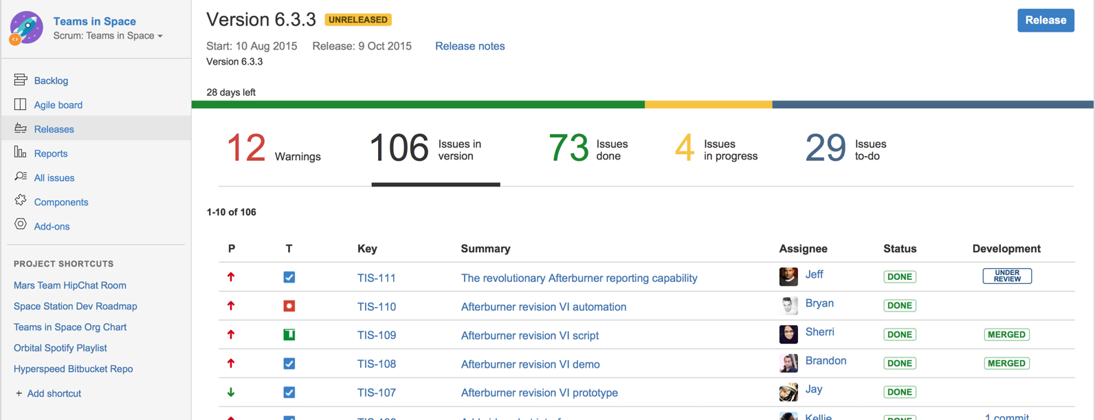
Issue trackers (sometimes called bug trackers) are commonly used to track task assignment and progress. Most online project management software such as GitHub, SourceForge, and BitBucket come with an integrated issue tracker.
A screenshot from the Jira Issue tracker software (Jira is part of the BitBucket project management tool suite):
Project Management → Project Planning → Work Breakdown Structure
Can explain work breakdown structures
A Work Breakdown Structure (WBS) depicts information about tasks and their details in terms of subtasks. When managing projects it is useful to divide the total work into smaller, well-defined units. Relatively complex tasks can be further split into subtasks. In complex projects a WBS can also include prerequisite tasks and effort estimates for each task.
The high level tasks for a single iteration of a small project could look like the following:
| Task ID | Task | Estimated Effort | Prerequisite Task |
|---|---|---|---|
| A | Analysis | 1 man day | - |
| B | Design | 2 man day | A |
| C | Implementation | 4.5 man day | B |
| D | Testing | 1 man day | C |
| E | Planning for next version | 1 man day | D |
The effort is traditionally measured in man hour/day/month i.e. work that can be done by one person in one hour/day/month. The Task ID is a label for easy reference to a task. Simple labeling is suitable for a small project, while a more informative labeling system can be adopted for bigger projects.
An example WBS for a project for developing a game.
| Task ID | Task | Estimated Effort | Prerequisite Task |
|---|---|---|---|
| A | High level design | 1 man day | - |
| B |
Detail design
|
2 man day
|
A |
| C |
Implementation
|
4.5 man day
|
|
| D | System Testing | 1 man day | C |
| E | Planning for next version | 1 man day | D |
All tasks should be well-defined. In particular, it should be clear as to when the task will be considered done.
Some examples of ill-defined tasks and their better-defined counterparts:
| Bad | Better |
|---|---|
| more coding | implement component X |
| do research on UI testing | find a suitable tool for testing the UI |
Which one these project tasks is not well-defined?
(c)
Explanation: ‘More testing’ is not well-defined. How much is ‘more’? ‘Test the delete functionality’ is a better-defined task.
Project Management → Project Planning → GANTT Charts
Can explain GANTT charts
A Gantt chart is a 2-D bar-chart, drawn as time vs tasks (represented by horizontal bars).
A sample Gantt chart:
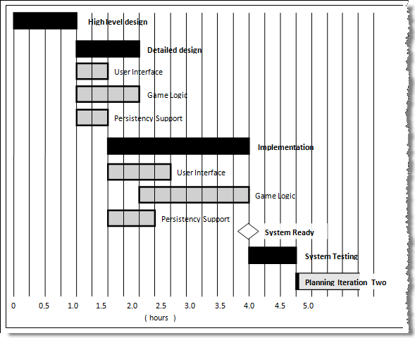
In a Gantt chart, a solid bar represents the main task, which is generally composed of a number of subtasks, shown as grey bars. The diamond shape indicates an important deadline/deliverable/milestone.
Project Management → Project Planning → PERT Charts
Can explain PERT charts
PERT (Program Evaluation Review Technique) chart uses a graphical technique to show the order/sequence of tasks. It is based on a simple idea of drawing a directed graph in which:
- Node or vertex captures the effort estimation of a task, and
- Arrow depicts the precedence between tasks
an example PERT chart for a simple software project
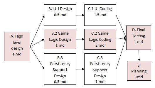
md = man days
A PERT chart can help determine the following important information:
- The order of tasks. In the example above,
Final Testingcannot begin until all coding of individual subsystems have been completed. - Which tasks can be done concurrently. In the example above, the various subsystem designs can start independently once the
High level designis completed. - The shortest possible completion time. In the example above, there is a path (indicated by the shaded boxes) from start to end that determines the shortest possible completion time.
- The Critical Path. In the example above, the shortest possible path is also the critical path.
Critical path is the path in which any delay can directly affect the project duration. It is important to ensure tasks on the critical path are completed on time.
Project Management → Teamwork → Team Structures
Can explain common team structures
Given below are three commonly used team structures in software development. Irrespective of the team structure, it is a good practice to assign roles and responsibilities to different team members so that someone is clearly in charge of each aspect of the project. In comparison, the ‘everybody is responsible for everything’ approach can result in more chaos and hence slower progress.
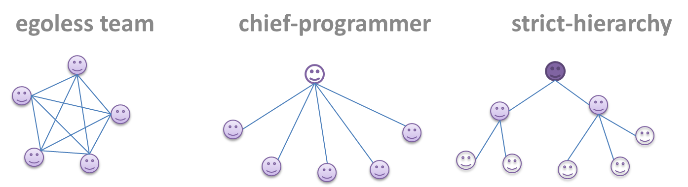
Egoless team
In this structure, every team member is equal in terms of responsibility and accountability. When any decision is required, consensus must be reached. This team structure is also known as a democratic team structure. This team structure usually finds a good solution to a relatively hard problem as all team members contribute ideas.
However, the democratic nature of the team structure bears a higher risk of falling apart due to the absence of an authority figure to manage the team and resolve conflicts.
Chief programmer team
Frederick Brooks proposed that software engineers learn from the medical surgical team in an operating room. In such a team, there is always a chief surgeon, assisted by experts in other areas. Similarly, in a chief programmer team structure, there is a single authoritative figure, the chief programmer. Major decisions, e.g. system architecture, are made solely by him/her and obeyed by all other team members. The chief programmer directs and coordinates the effort of other team members. When necessary, the chief will be assisted by domain specialists e.g. business specialists, database expert, network technology expert, etc. This allows individual group members to concentrate solely on the areas where they have sound knowledge and expertise.
The success of such a team structure relies heavily on the chief programmer. Not only must he be a superb technical hand, he also needs good managerial skills. Under a suitably qualified leader, such a team structure is known to produce successful work. .
Strict hierarchy team
In the opposite extreme of an egoless team, a strict hierarchy team has a strictly defined organization among the team members, reminiscent of the military or bureaucratic government. Each team member only works on his assigned tasks and reports to a single “boss”.
In a large, resource-intensive, complex project, this could be a good team structure to reduce communication overhead.
Which team structure is the most suitable for a school project?
(a)
Explanation: Given that students are all peers and beginners, Egoless team structure seems most suitable for a school project. However, given school projects are low-stakes, short-lived, and small, even the other two team structures can be used for them.
Project Management → Revision Control → Forking Flow
Can explain forking workflow
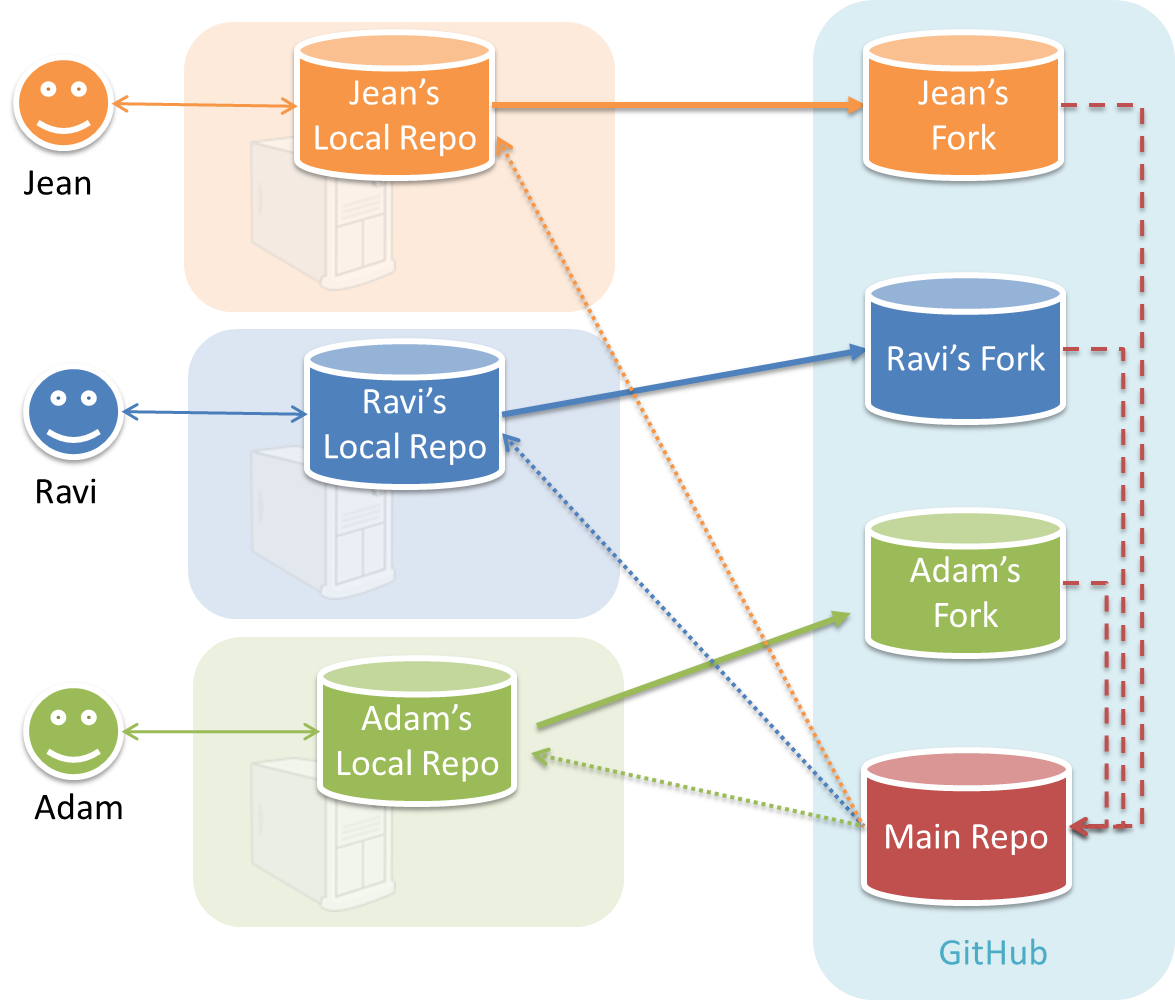
In the forking workflow, the 'official' version of the software is kept in a remote repo designated as the 'main repo'. All team members fork the main repo create pull requests from their fork to the main repo.
To illustrate how the workflow goes, let’s assume Jean wants to fix a bug in the code. Here are the steps:
- Jean creates a separate branch in her local repo and fixes the bug in that branch.
- Jean pushes the branch to her fork.
- Jean creates a pull request from that branch in her fork to the main repo.
- Other members review Jean’s pull request.
- If reviewers suggested any changes, Jean updates the PR accordingly.
- When reviewers are satisfied with the PR, one of the members (usually the team lead or a designated 'maintainer' of the main repo) merges the PR, which brings Jean’s code to the main repo.
- Other members, realizing there is new code in the upstream repo, sync their forks with the new upstream repo (i.e. the main repo). This is done by pulling the new code to their own local repo and pushing the updated code to their own fork.
- A detailed explanation of the Forking Workflow - From Atlassian
Tools → Git and GitHub → Forking Workflow
Can follow Forking Workflow
This activity is best done as a team. If you are learning this alone, you can simulate a team by using two different browsers to log into GitHub using two different accounts.
-
One member: set up the team org and the team repo.
- Create a GitHub organization for your team. The org name is up to you. We'll refer to this organization as team org from now on.
- Add a team called
developersto your team org. - Add your team members to the
developersteam. - Fork se-edu/samplerepo-workflow-practice to your team org. We'll refer to this as the team repo.
- Add the forked repo to the
developersteam. Give write access.
-
Each team member: create PRs via own fork
- Fork that repo from your team org to your own GitHub account.
- Create a PR to add a file
yourName.md(e.g.jonhDoe.md) containing a brief resume of yourself (branch → commit → push → create PR)
-
For each PR: review, update, and merge.
- A team member (not the PR author): Review the PR by adding comments (can be just dummy comments).
- PR author: Update the PR by pushing more commits to it, to simulate updating the PR based on review comments.
- Another team member: Merge the PR using the GitHub interface.
- All members: Sync your local repo (and your fork) with upstream repo. In this case, your upstream repo is the repo in your team org.
-
Create conflicting PRs.
- Each team member: Create a PR to add yourself under the
Team Memberssection in theREADME.md. - One member: in the
masterbranch, remove John Doe and Jane Doe from theREADME.md, commit, and push to the main repo.
- Each team member: Create a PR to add yourself under the
-
Merge conflicting PRs one at a time. Before merging a PR, you’ll have to resolve conflicts. Steps:
- [Optional] A member can inform the PR author (by posting a comment) that there is a conflict in the PR.
- PR author: Pull the
masterbranch from the repo in your team org. Merge the pulledmasterbranch to your PR branch. Resolve the merge conflict that crops up during the merge. Push the updated PR branch to your fork. - Another member or the PR author: When GitHub does not indicate a conflict anymore, you can go ahead and merge the PR.
Project Management → Revision Control → DRCS vs CRCS
Can explain DRCS vs CRCS
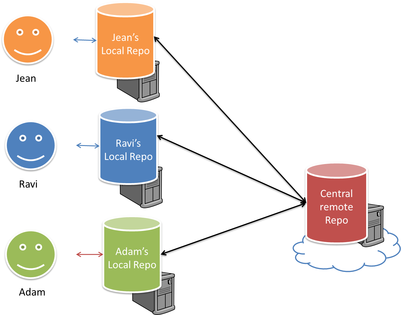
RCS can be done in two ways: the centralized way and the distributed way.
Centralized RCS (CRCS for short)uses a central remote repo that is shared by the team. Team members download (‘pull’) and upload (‘push’) changes between their own local repositories and the central repository. Older RCS tools such as CVS and SVN support only this model. Note that these older RCS do not support the notion of a local repo either. Instead, they force users to do all the versioning with the remote repo.
The centralized RCS approach without any local repos (e.g., CVS, SVN)
Distributed RCS (DRCS for short, also known as Decentralized RCS) allows multiple remote repos and pulling and pushing can be done among them in arbitrary ways. The workflow can vary differently from team to team. For example, every team member can have his/her own remote repository in addition to their own local repository, as shown in the diagram below. Git and Mercurial are some prominent RCS tools that support the distributed approach.
The decentralized RCS approach
Project Management → Revision Control → Feature Branch Flow
Can explain feature branch flow
Feature branch workflow is similar to forking workflow except there are no forks. Everyone is pushing/pulling from the same remote repo. The phrase feature branch is used because each new feature (or bug
fix, or any other modification) is done in a separate branch and merged to master branch when ready.
- A detailed explanation of the Feature Branch Workflow - From Atlassian
Project Management → Revision Control → Centralized Flow
Can explain centralized flow
The centralized workflow is similar to the feature branch workflow except all changes are done in the master branch.
- A detailed explanation of the Centralized Workflow - From Atlassian