This site is not ready yet! The updated version will be available soon.
CS2103/T 2020 Jan-Apr
  • Full Timeline
  • Week 1 [Aug 12]
  • Week 2 [Aug 19]
  • Week 3 [Aug 26]
  • Week 4 [Sep 2]
  • Week 5 [Sep 9]
  • Week 6 [Sep 16]
  • Week 7 [Sep 30]
  • Week 8 [Oct 7]
  • Week 9 [Oct 14]
  • Week 10 [Oct 21]
  • Week 11 [Oct 28]
  • Week 12 [Nov 4]
  • Week 13 [Nov 11]
  • Textbook
  • Admin Info
  • Report Bugs
  • Forum
  • Instructors
  • Announcements
  • File Submissions
  • Tutorial Schedule
  • Java Coding Standard
  • Participation Marks List

  •  Individual Project (iP):
  • Individual Project Info
  • Duke Upstream Repo
  • iP Code Dashboard
  • iP Showcase

  •  Team Project (tP):
  • Team Project Info
  • Team IDs
  • Addressbook-level3
  • Addressbook-level 1,2,4
  • tP Code Dashboard
  • tP Showcase
  • Week 4 [Sep 2] - Topics

    • [W4.1] Design: Models
    • [W4.1a] Design → Modelling → Introduction → What

    • [W4.1b] Design → Modelling → Introduction → How

    • [W4.1c] Design → Modelling → Introduction → UML Models

    • [W4.2] Class/Object Diagrams: Basics
    • [W4.2a] Design → Modelling → Modelling Structure → OO Structures

    • [W4.2b] Design → Modelling → Modelling Structure → Class Diagrams (Basics)

    • [W4.2c] Design → Modelling → Modelling Structure → Object Diagrams

    • [W4.2d] Tools → UML → Object vs Class Diagrams

    • [W4.3] Class Diagrams: Intermediate-Level
    • [W4.3a] Tools → UML → Notes

    • [W4.3b] Tools → UML → Constraints

    • [W4.3c] Tools → UML → Class Diagrams → Associations as Attributes

    • [W4.3d] Design → Modelling → Modelling Structure → Class Diagrams - Intermediate

    • [W4.3e] Paradigms → OOP → Associations → Association Classes

    • [W4.4] Java: JavaFX
    • [W4.4a] Tools → Java → JavaFX
    • [W4.5] Java: varargs
    • [W4.5a] Tools → Java → Varargs :

    • [W4.6] RCS: Managing Pull Requests
    • [W4.6a] Tools → Git and GitHub → Manage PRs

    • [W4.7] Code reviews
    • [W4.7a] Quality Assurance → Quality Assurance → Code Reviews → What
    • [W4.8] Static Analysis
    • [W4.8a] Quality Assurance → Quality Assurance → Static Analysis → What


    [W4.1] Design: Models

    W4.1a

    Design → Modelling → Introduction → What

    Can explain models

    A model is a representation of something else.

    A class diagram is a model that represents a software design.

    A class diagram is a diagram drawn using the UML modelling notation.
    An example class diagram:

    A model provides a simpler view of a complex entity because a model captures only a selected aspect. This omission of some aspects implies models are abstractions.

    Design → Design Fundamentals → Abstraction →

    What

    Abstraction is a technique for dealing with complexity. It works by establishing a level of complexity we are interested in, and suppressing the more complex details below that level.

    The guiding principle of abstraction is that only details that are relevant to the current perspective or the task at hand needs to be considered. As most programs are written to solve complex problems involving large amounts of intricate details, it is impossible to deal with all these details at the same time. That is where abstraction can help.

    Data abstraction: abstracting away the lower level data items and thinking in terms of bigger entities

    Within a certain software component, we might deal with a user data type, while ignoring the details contained in the user data item such as name, and date of birth. These details have been ‘abstracted away’ as they do not affect the task of that software component.

    Control abstraction: abstracting away details of the actual control flow to focus on tasks at a higher level

    print(“Hello”) is an abstraction of the actual output mechanism within the computer.

    Abstraction can be applied repeatedly to obtain progressively higher levels of abstractions.

    An example of different levels of data abstraction: a File is a data item that is at a higher level than an array and an array is at a higher level than a bit.

    An example of different levels of control abstraction: execute(Game) is at a higher level than print(Char) which is at a higher than an Assembly language instruction MOV.

    Abstraction is a general concept that is not limited to just data or control abstractions.

    Some more general examples of abstraction:

    • An OOP class is an abstraction over related data and behaviors.
    • An architecture is a higher-level abstraction of the design of a software.
    • Models (e.g., UML models) are abstractions of some aspect of reality.

    A class diagram captures the structure of the software design but not the behavior.

    Multiple models of the same entity may be needed to capture it fully.

    In addition to a class diagram (or even multiple class diagrams), a number of other diagrams may be needed to capture various interesting aspects of the software.

    W4.1b

    Design → Modelling → Introduction → How

    Can explain how models are used

    In software development, models are useful in several ways:

    a) To analyze a complex entity related to software development.

    Some examples of using models for analysis:

    1. Models of the problem domain can be built to aid the understanding of the problem to be solved.
    2. When planning a software solution, models can be created to figure out how the solution is to be built. An architecture diagram is such a model.

    An architecture diagram depicts the high-level design of a software.

    b) To communicate information among stakeholders. Models can be used as a visual aid in discussions and documentations.

    Some examples of using models to communicate:

    1. We can use an architecture diagram to explain the high-level design of the software to developers.
    2. A business analyst can use a use case diagram to explain to the customer the functionality of the system.
    3. A class diagram can be reverse-engineered from code so as to help explain the design of a component to a new developer.

    c) As a blueprint for creating software. Models can be used as instructions for building software.

    Some examples of using models to as blueprints:

    1. A senior developer draws a class diagram to propose a design for an OOP software and passes it to a junior programmer to implement.
    2. A software tool allows users to draw UML models using its interface and the tool automatically generates the code based on the model.
    Model Driven Development extra

    Model-driven development (MDD), also called Model-driven engineering, is an approach to software development that strives to exploit models as blueprints. MDD uses models as primary engineering artifacts when developing software. That is, the system is first created in the form of models. After that, the models are converted to code using code-generation techniques (usually, automated or semi-automated, but can even involve manual translation from model to code). MDD requires the use of a very expressive modeling notation (graphical or otherwise), often specific to a given problem domain. It also requires sophisticated tools to generate code from models and maintain the link between models and the code. One advantage of MDD is that the same model can be used to create software for different platforms and different languages. MDD has a lot of promise, but it is still an emerging technology

    Further reading:

    Choose the correct statements about models.

    • a. Models are abstractions.
    • b. Models can be used for communication.
    • c. Models can be used for analysis of a problem.
    • d. Generating models from code is useless.
    • e. Models can be used as blueprints for generating code.

    (a) (b) (c) (e)

    Explanation: Models generated from code can be used for understanding, analysing, and communicating about the code.

    Explain how models (e.g. UML diagrams) can be used in a class project.

    Can models be useful in evaluating the design quality of a software written by students?

    W4.1c

    Design → Modelling → Introduction → UML Models

    Can identify UML models

    The following diagram uses the class diagram notation to show the different types of UML diagrams.

    Unified Modeling Language (UML) is a graphical notation to describe various aspects of a software system. UML is the brainchild of three software modeling specialists James Rumbaugh, Grady Booch and Ivar Jacobson (also known as the Three Amigos). Each of them has developed their own notation for modeling software systems before joining force to create a unified modeling language (hence, the term ‘Unified’ in UML). UML is currently the de facto modeling notation used in the software industry.


    source:https://en.wikipedia.org/

    [W4.2] Class/Object Diagrams: Basics

    W4.2a

    Design → Modelling → Modelling Structure → OO Structures

    Can explain structure modelling of OO solutions

    An OO solution is basically a network of objects interacting with each other. Therefore, it is useful to be able to model how the relevant objects are 'networked' together inside a software i.e. how the objects are connected together.

    Given below is an illustration of some objects and how they are connected together. Note: the diagram uses an ad-hoc notation.

    Note that these object structures within the same software can change over time.

    Given below is how the object structure in the previous example could have looked like at a different time.

    However, object structures do not change at random; they change based on a set of rules, as was decided by the designer of that software. Those rules that object structures need to follow can be illustrated as a class structure i.e. a structure that exists among the relevant classes.

    Here is a class structure (drawn using an ad-hoc notation) that matches the object structures given in the previous two examples. For example, note how this class structure does not allow any connection between Genre objects and Author objects, a rule followed by the two object structures above.

    UML Object Diagrams are used to model object structures and UML Class Diagrams are used to model class structures of an OO solution.

    Here is an object diagram for the above example:

    And here is the class diagram for it:

    W4.2b

    Design → Modelling → Modelling Structure → Class Diagrams (Basics)

    Can use basic-level class diagrams

    Classes form the basis of class diagrams.

    Associations are the main connections among the classes in a class diagram.

    The most basic class diagram is a bunch of classes with some solid lines among them to represent associations, such as this one.

    An example class diagram showing associations between classes.

    In addition, associations can show additional decorations such as association labels, association roles, multiplicity and navigability to add more information to a class diagram.

    Here is the same class diagram shown earlier but with some additional information included:

    Which association notations are shown in this diagram?

    • a. association labels
    • b. association roles
    • c. association multiplicity
    • d. class names

    (a) (b) (c) (d)

    Explanation: '1’ is a multiplicity, ‘mentored by’ is a label, and ‘mentor’ is a role.

    Explain the associations, navigabilities, and multiplicities in the class diagram below:

    Draw a class diagram for the code below. Show the attributes, methods, associations, navigabilities, and multiplicities in the class diagram below:

    class Box {
        private Item[] parts = new Item[10];
        private Item spareItem;
        private Lid lid; // lid of this box
        private Box outerBox;
    
        public void open(){
            //...
        }
    }
    
    class Item {
        public static int totalItems;
    }
    
    class Lid {
        Box box; // the box for which this is the lid
    }
    

    W4.2c

    Design → Modelling → Modelling Structure → Object Diagrams

    Can use basic object diagrams

    Object diagrams can be used to complement class diagrams. For example, you can use object diagrams to model different object structures that can result from a design represented by a given class diagram.

    This question is based on the following question from another topic:

    Draw a class diagram for the code below. Show the attributes, methods, associations, navigabilities, and multiplicities in the class diagram below:

    class Box {
        private Item[] parts = new Item[10];
        private Item spareItem;
        private Lid lid; // lid of this box
        private Box outerBox;
    
        public void open(){
            //...
        }
    }
    
    class Item {
        public static int totalItems;
    }
    
    class Lid {
        Box box; // the box for which this is the lid
    }
    

    Draw an object diagram to match the code. Include objects of all three classes in your object diagram.

    W4.2d

    Tools → UML → Object vs Class Diagrams

    Can distinguish between class diagrams and object diagrams

    Compared to the notation for a class diagrams, object diagrams differ in the following ways:

    • Shows objects instead of classes:
      • Instance name may be shown
      • There is a : before the class name
      • Instance and class names are underlined
    • Methods are omitted
    • Multiplicities are omitted

    Furthermore, multiple object diagrams can correspond to a single class diagram.

    Both object diagrams are derived from the same class diagram shown earlier. In other words, each of these object diagrams shows ‘an instance of’ the same class diagram.

    Which of these class diagrams match the given object diagram?

    • a
    • b

    (a) (b)

    Explanation: Both class diagrams allow one Unit object to be linked to one Item object.

    [W4.3] Class Diagrams: Intermediate-Level

    W4.3a

    Tools → UML → Notes

    Can use UML notes

    UML notes can augment UML diagrams with additional information. These notes can be shown connected to a particular element in the diagram or can be shown without a connection. The diagram below shows examples of both.

    Example:

    W4.3b

    Tools → UML → Constraints

    Can specify constraints in UML diagrams

    A constraint can be given inside a note, within curly braces. Natural language or a formal notation such as OCL (Object Constraint Language) may be used to specify constraints.

    Example:

    W4.3c

    Tools → UML → Class Diagrams → Associations as Attributes

    Can show an association as an attribute

    An association can be shown as an attribute instead of a line.

    Association multiplicities and the default value too can be shown as part of the attribute using the following notation. Both are optional.

    name: type [multiplicity] = default value

    The diagram below depicts a multi-player Square Game being played on a board comprising of 100 squares. Each of the squares may be occupied with any number of pieces, each belonging to a certain player.

    A Piece may or may not be on a Square. Note how that association can be replaced by an isOn attribute of the Piece class. The isOn attribute can either be null or hold a reference to a Square object, matching the 0..1 multiplicity of the association it replaces. The default value is null.

    The association that a Board has 100 Squares can be shown in either of these two ways:

    Show each association as either an attribute or a line but not both. A line is preferred is it is easier to spot.

    W4.3d

    Design → Modelling → Modelling Structure → Class Diagrams - Intermediate

    Can use intermediate-level class diagrams

    A class diagram can also show different types of relationships between classes: inheritance, compositions, aggregations, dependencies.

    Modeling inheritance

    Modeling composition

    Modeling aggregation

    Modeling dependencies

    A class diagram can also show different types of class-like entities:

    Modeling enumerations

    Modeling abstract classes

    Modeling interfaces

    Which of these statements match the class diagram?

    • a. A Snake must belong to at least one Board.
    • b. A SnakeHeadSquare can contain only one Snake head.
    • c. A Square can contain a Snake head.
    • d. A Snake head can be in more than one SnakeHeadSquare
    • e. The Board has exactly 5 Snakes.

    (a)(b)(c)(d)(e)

    Explanation:

    (a) does not match because a Snake may or may not belong to a Board (multiplicity is 0..1)
    (b) matches the diagram because the multiplicity given in 1
    (c) matches the diagram because SnakeHeadSquare is a Square (due to inheritance)
    (d) matches the diagram because the multiplicity given is *
    (e) matches the diagram because the multiplicity given in 5

    Explain the meaning of various class diagram notations in the following class diagram:

    Consider the code below:

    public interface Billable {
        void bill();
    }
    
    public abstract class Item
             implements Billable {
        public abstract void print();
    }
    
    public class StockItem extends Item {
        private Review review;
        private String name;
    
        public StockItem(
            String name, Rating rating){
    
            this.name = name;
            this.review = new Review(rating);
        }
    
        @Override
        public void print() {
            //...
        }
    
        @Override
        public void bill() {
            //...
        }
    }
    
    public enum Rating {
        GOOD, OK, POOR
    }
    
    public class Review {
        private final Rating rating;
    
        public Review(Rating rating) {
            this.rating = rating;
        }
    }
    
    import java.util.List;
    
    public class Inventory {
        private List<Item> items;
    
        public int getItemCount(){
            return items.size();
        }
    
        public void generateBill(Billable b){
            // ...
        }
    
        public void add(Item s) {
            items.add(s);
        }
    }
    

    (a) Draw a class diagram to represent the code. Show all attributes, methods, associations, navigabilities, visibilities, known multiplicities, and association roles. Show associations as lines.
    (b) Draw an object diagram to represent the situation where the inventory has one item with a name spanner and a review of POOR rating.

    W4.3e

    Paradigms → OOP → Associations → Association Classes

    Can explain the meaning of association classes

    An association class represents additional information about an association. It is a normal class but plays a special role from a design point of view.

    A Man class and a Woman class is linked with a ‘married to’ association and there is a need to store the date of marriage. However, that data is related to the association rather than specifically owned by either the Man object or the Woman object. In such situations, an additional association class can be introduced, e.g. a Marriage class, to store such information.

    Implementing association classes

    There is no special way to implement an association class. It can be implemented as a normal class that has variables to represent the endpoint of the association it represents.

    In the code below, the Transaction class is an association class that represent a transaction between a Person who is the seller and another Person who is the buyer.

    class Transaction{
        
        //all fields are compulsory
        Person seller;
        Person buyer;
        Date date;
        String receiptNumber;
        
        Transaction (Person seller, Person buyer, Date date, String receiptNumber){
            //set fields
        }
    }
    

    Which one of these is the suitable as an Association Class?

    • a
    • b
    • c
    • d

    (a)(b)(c)(d)

    Explanation: Mileage is a property of the car, and not specifically about the association between the Driver and the Car. If Mileage was defined as the total number of miles that car was driven by that driver, then it would be suitable as an association class.

    [W4.4] Java: JavaFX

    W4.4a

    Tools → Java → JavaFX

    Can use JavaFX to build a simple GUI

    JavaFX is a technology for building Java-based GUIs. Previously it was a part Java itself, but has become a third-party dependency since then. It is now being maintained by OpenJDK.

    [W4.5] Java: varargs

    W4.5a :

    Tools → Java → Varargs

    Can use Java varargs feature

    Variable Arguments (Varargs) is a syntactic sugar type feature that allows writing a methods that can take a variable number of arguments.

    The search method below can be called as search(), search("book"), search("book", "paper"), etc.

    public static void search(String ... keywords){
       // method body
    }
    

    Resources:

    [W4.6] RCS: Managing Pull Requests

    W4.6a

    Tools → Git and GitHub → Manage PRs

    Can review and merge PRs on GitHub

    1. Go to the GitHub page of your fork and review the add-intro PR you created previously in [ Tools → Git & GitHub → Create PRs] to simulate the PR being reviewed by another developer, as explained below. Note that some features available to PR reviewers will be unavailable to you because you are also the author of the PR.

    1. Fork the samplerepo-pr-practice onto your GitHub account. Clone it onto your computer.

    2. Create a branch named add-intro in your clone. Add a couple of commits which adds/modifies an Introduction section to the README.md. Example:

    
    # Introduction
    Creating Pull Requsts (PRs) is needed when using RCS in a multi-person projects.
    This repo can be used to practice creating PRs.


    3. Push the add-intro branch to your fork.

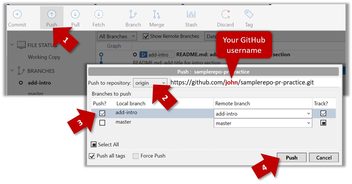
    git push origin add-intro
    

    4. Create a Pull Request from the add-intro branch in your fork to the master branch of the same fork (i.e. your-user-name/samplerepo-pr-practice, not se-edu/samplerepo-pr-practice), as described below.

    4a. Go to the GitHub page of your fork (i.e. https://github.com/{your_username}/samplerepo-pr-practice), click on the Pull Requests tab, and then click on New Pull Request button.

    4b. Select base fork and head fork as follows:

    • base fork: your own fork (i.e. {your user name}/samplerepo-pr-practice, NOT se-edu/samplerepo-pr-practice)
    • head fork: your own fork.

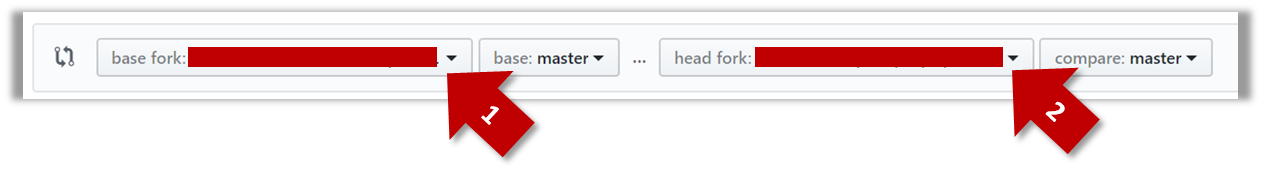
    The base fork is where changes should be applied. The head fork contains the changes you would like to be applied.

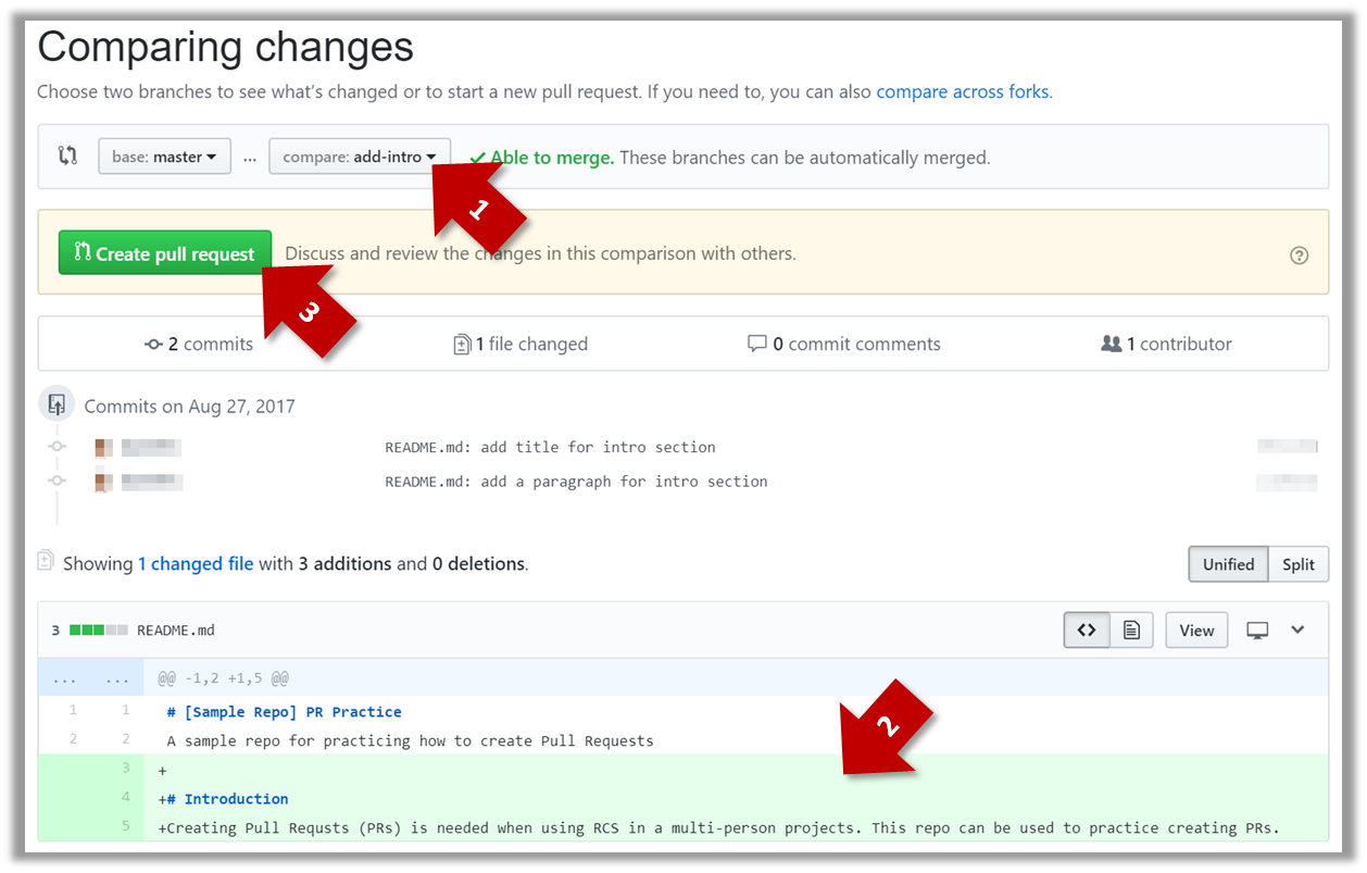
    4c. (1) Set the base branch to master and head branch to add-intro, (2) confirm the diff contains the changes you propose to merge in this PR (i.e. confirm that you did not accidentally include extra commits in the branch), and (3) click the Create pull request button.

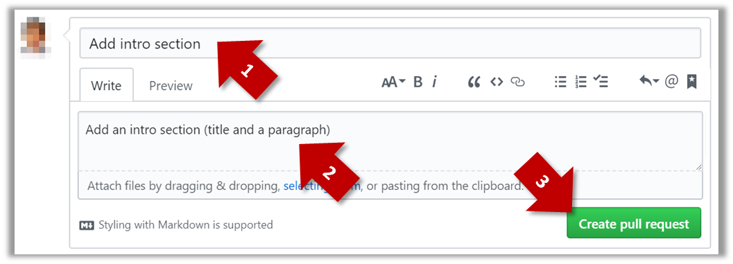
    4d. (1) Set PR name, (2) set PR description, and (3) Click the Create pull request button.

    A common newbie mistake when creating branch-based PRs is to mix commits of one PR with another. To learn how to avoid that mistake, you are encouraged to continue and create another PR as explained below.

    5. In your local repo, create a new branch add-summary off the master branch.

    When creating the new branch, it is very important that you switch back to the master branch first. If not, the new branch will be created off the current branch add-intro. And that is how you end up having commits of the first PR in the second PR as well.

    6. Add a commit in the add-summary branch that adds a Summary section to the README.md, in exactly the same place you added the Introduction section earlier.

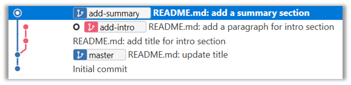
    7. Push the add-summary to your fork and create a new PR similar to before.

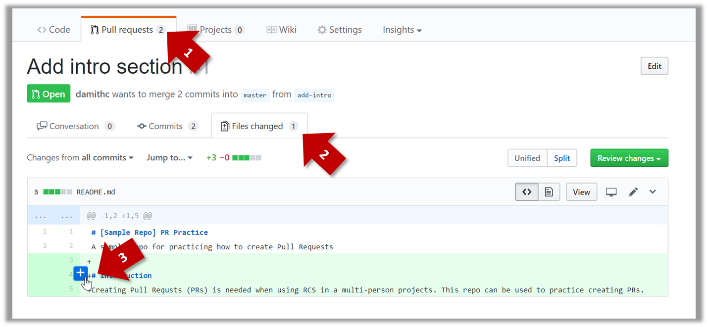
    1a. Go to the respective PR page and click on the Files changed tab. Hover over the line you want to comment on and click on the icon that appears on the left margin. That should create a text box for you to enter your comment.

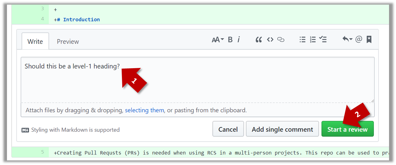
    1b. Enter some dummy comment and click on Start a review button.

    1c. Add a few more comments in other places of the code.

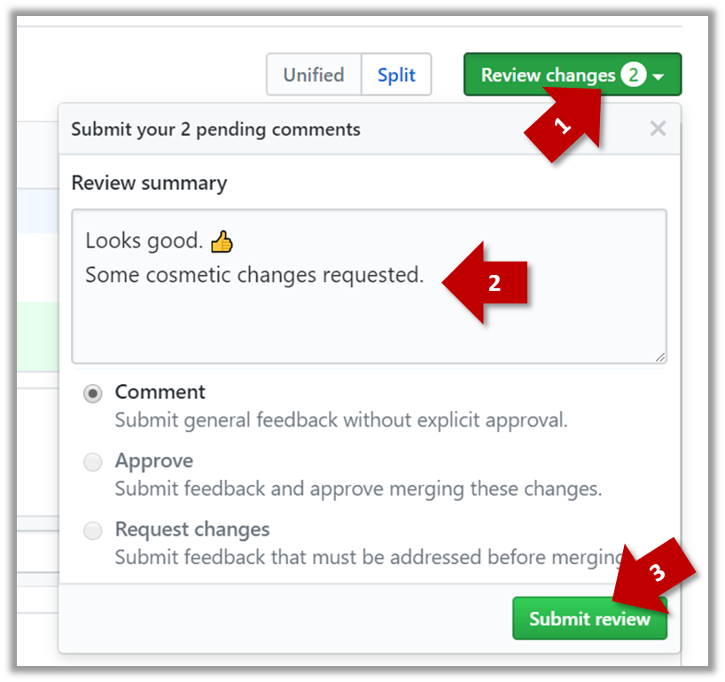
    1d. Click on the Review Changes button, enter an overall comment, and click on the Submit review button.

    2. Update the PR to simulate revising the code based on reviewer comments. Add some more commits to the add-intro branch and push the new commits to the fork. Observe how the PR is updated automatically to reflect the new code.

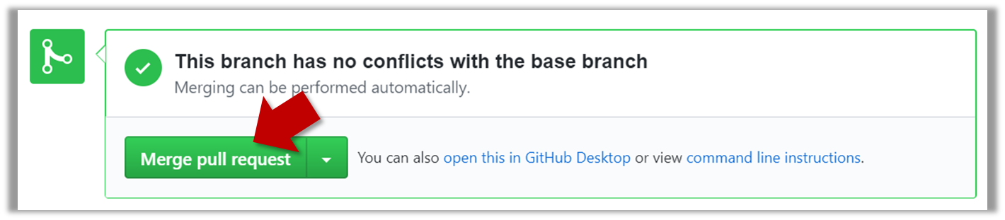
    3. Merge the PR. Go to the GitHub page of the respective PR, scroll to the bottom of the Conversation tab, and click on the Merge pull request button, followed by the Confirm merge button. You should see a Pull request successfully merged and closed message after the PR is merged.

    4. Sync the local repo with the remote repo. Because of the merge you did on the GitHub, the master branch of your fork is now ahead of your local repo by one commit. To sync the local repo with the remote repo, pull the master branch to the local repo.

    git checkout master
    git pull origin master
    

    Observe how the add-intro branch is now merged to the master branch in your local repo as well.

    5. De-conflict the add-summary PR that you created earlier. Note that GitHub page for the add-summary PR is now showing a conflict (when you scroll to the bottom of that page, you should see a message This branch has conflicts that must be resolved). You can resolve it locally and update the PR accordingly, as explained below.

    5a. Switch to the add-summary branch. To make that branch up-to-date with the master branch, merge the master branch to it, which will surface the merge conflict. Resolve it and complete the merge.

    5b. Push the updated add-summary branch to the fork. That will remove the 'merge conflicts' warning in the GitHub page of the PR.

    6. Merge the add-summary PR using the GitHub interface, similar to how you merged the previous PR.

    Note that you could have merged the add-summary branch to the master branch locally before pushing it to GitHub. In that case, the PR will be merged on GitHub automatically to reflect that the branch has been merged already.

    [W4.7] Code reviews

    W4.7a

    Quality Assurance → Quality Assurance → Code Reviews → What

    Can explain code reviews

    Code review is the systematic examination code with the intention of finding where the code can be improved.

    Reviews can be done in various forms. Some examples below:

    • Pull Request reviews

      • Project Management Platforms such as GitHub and BitBucket allow the new code to be proposed as Pull Requests and provide the ability for others to review the code in the PR.
    • In pair programming

      • As pair programming involves two programmers working on the same code at the same time, there is an implicit review of the code by the other member of the pair.

    Pair Programming:

    Pair programming is an agile software development technique in which two programmers work together at one workstation. One, the driver, writes code while the other, the observer or navigator, reviews each line of code as it is typed in. The two programmers switch roles frequently. [source: Wikipedia]


    [image credit: Wikipedia]

    A good introduction to pair programming:

    • Formal inspections

      • Inspections involve a group of people systematically examining a project artifacts to discover defects. Members of the inspection team play various roles during the process, such as:

        • the author - the creator of the artifact
        • the moderator - the planner and executor of the inspection meeting
        • the secretary - the recorder of the findings of the inspection
        • the inspector/reviewer - the one who inspects/reviews the artifact.

    Advantages of code reviews over testing:

    • It can detect functionality defects as well as other problems such as coding standard violations.
    • Can verify non-code artifacts and incomplete code
    • Do not require test drivers or stubs.

    Disadvantages:

    • It is a manual process and therefore, error prone.

    [W4.8] Static Analysis

    W4.8a

    Quality Assurance → Quality Assurance → Static Analysis → What

    Can explain static analysis

    Static analysis: Static analysis is the analysis of code without actually executing the code.

    Static analysis of code can find useful information such unused variables, unhandled exceptions, style errors, and statistics. Most modern IDEs come with some inbuilt static analysis capabilities. For example, an IDE can highlight unused variables as you type the code into the editor.

    Higher-end static analyzer tools can perform more complex analysis such as locating potential bugs, memory leaks, inefficient code structures etc.

    Some example static analyzer for Java: CheckStyle, PMD, FindBugs

    Linters are a subset of static analyzers that specifically aim to locate areas where the code can be made 'cleaner'.