This is a printer-friendly version. It omits exercises, optional topics (i.e., four-star topics), and other extra content such as learning outcomes.
What
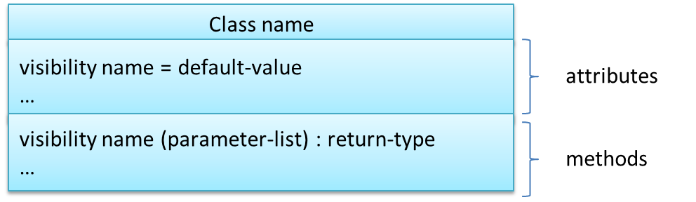
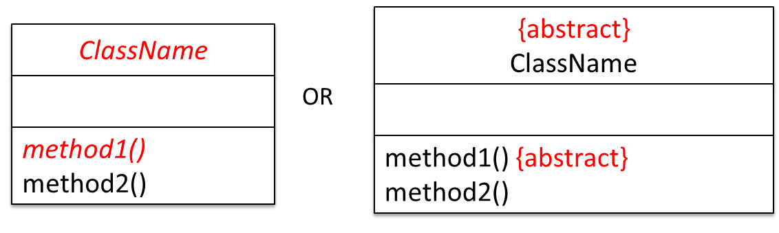
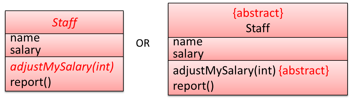
The basic UML notations used to represent a class:
A Table class shown in UML notation:
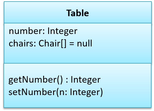
class Table{

    Integer number;
    Chair[] chairs = null;

    Integer getNumber(){
        //...
    }

    void setNumber(Integer n){
        //...
    }
}
class Table:

  def __init__(self):
    self.number = 0
    self.chairs = []

  def get_number(self):
    # ...

  def set_number(self, n):
    # ...
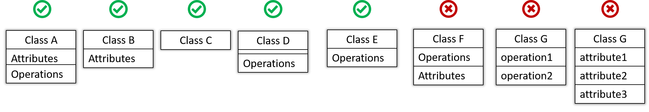
The 'Operations' compartment and/or the 'Attributes' compartment may be omitted if such details are not important for the task at hand. 'Attributes' always appear above the 'Operations' compartment. All operations should be in one compartment rather than each operation in a separate compartment. Same goes for attributes.
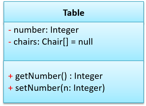
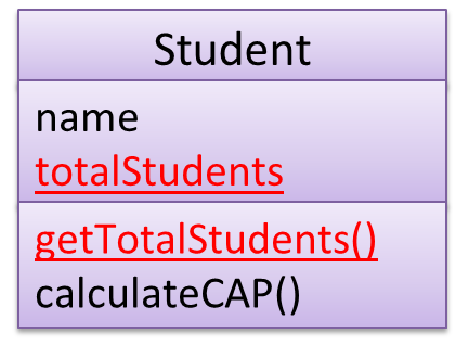
The visibility of attributes and operations is used to indicate the level of access allowed for each attribute or operation. The types of visibility and their exact meanings depend on the programming language used. Here are some common visibilities and how they are indicated in a class diagram:
+: public-: private#: protected~: package private
| visibility | Java | Python |
|---|---|---|
- private |
private |
at least two leading underscores (and at most one trailing underscores) in the name |
# protected |
protected |
one leading underscore in the name |
+ public |
public |
all other cases |
~ package private |
default visibility | not applicable |
Table class with visibilities shown:
What
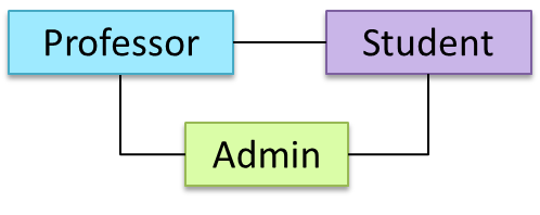
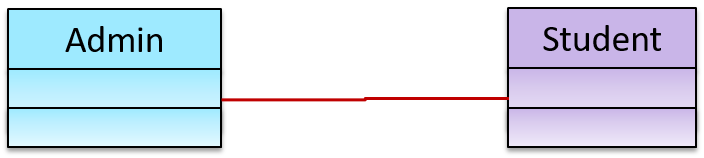
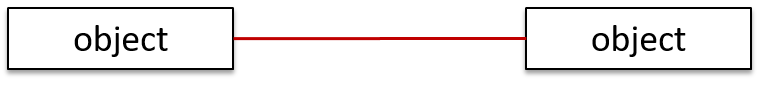
We use a solid line to show an association between two classes.
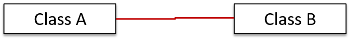
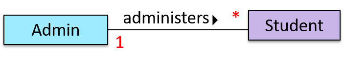
This example shows an association between the Admin class and the Student class:
Navigability
We use arrow heads to indication the navigability of an association.
Logic is aware of Minefield, but Minefield is not aware of Logic
class Logic{
    Minefield minefield;
}

class Minefield{
    ...
}
class Logic:

  def __init__(self, minefield):
    self.minefield = minefield

  # ...


class Minefield:
  # ...
Here is an example of a bidirectional navigability; each class is aware of the other.
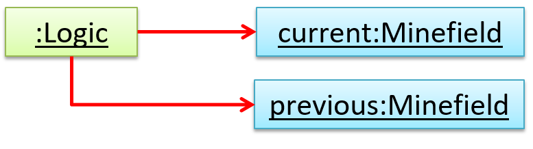
Navigability can be shown in class diagrams as well as object diagrams.
According to this object diagram the given Logic object is associated with and aware of two MineField objects.
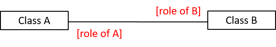
Roles
Association Role labels are used to indicate the role played by the classes in the association.
This association represents a marriage between a Man object and a Woman object. The respective roles played by objects of these two classes
are husband and wife.
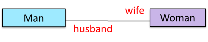
Note how the variable names match closely with the association roles.
class Man{
    Woman wife;
}

class Woman{
    Man husband;
}
class Man:
  def __init__(self):
    self.wife = None # a Woman object

class Woman:
   def __init__(self):
     self.husband = None # a Man object
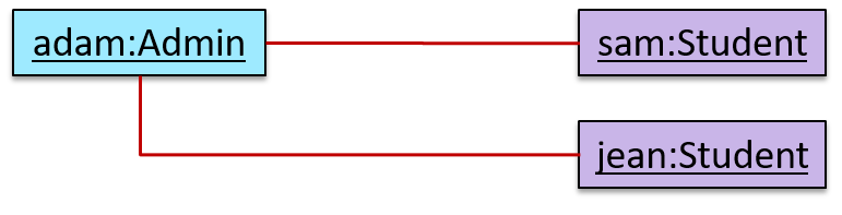
The role of Student objects in this association is charges (i.e. Admin is in charge of students)
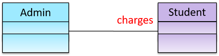
class Admin{
    List<Student> charges;
}
class Admin:
  def __init__(self):
    self.charges = [] # list of Student objects
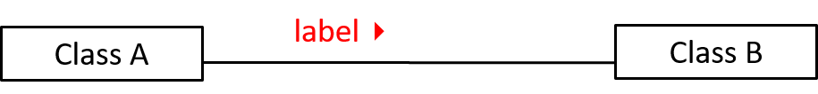
Labels
Association labels describe the meaning of the association. The arrow head indicates the direction in which the label is to be read.
In this example, the same association is described using two different labels.
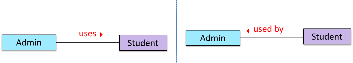
- Diagram on the left:
Adminclass is associated withStudentclass because anAdminobject uses aStudentobject. - Diagram on the right:
Adminclass is associated withStudentclass because aStudentobject is used by anAdminobject.
Multiplicity
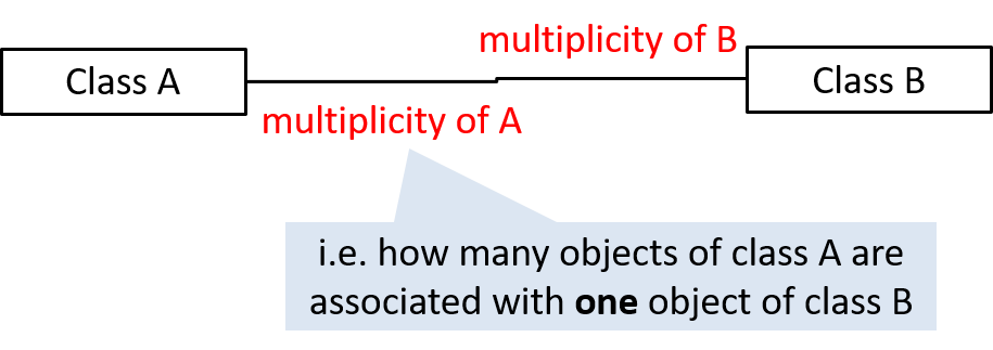
Commonly used multiplicities:
0..1: optional, can be linked to 0 or 1 objects1: compulsory, must be linked to one object at all times.*: can be linked to 0 or more objects.n..m: the number of linked objects must bentominclusive
In the diagram below, an Admin object administers (in charge of) any number of students but a Student object must always be under the charge
of exactly one Admin object
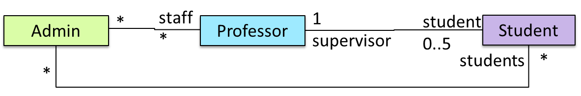
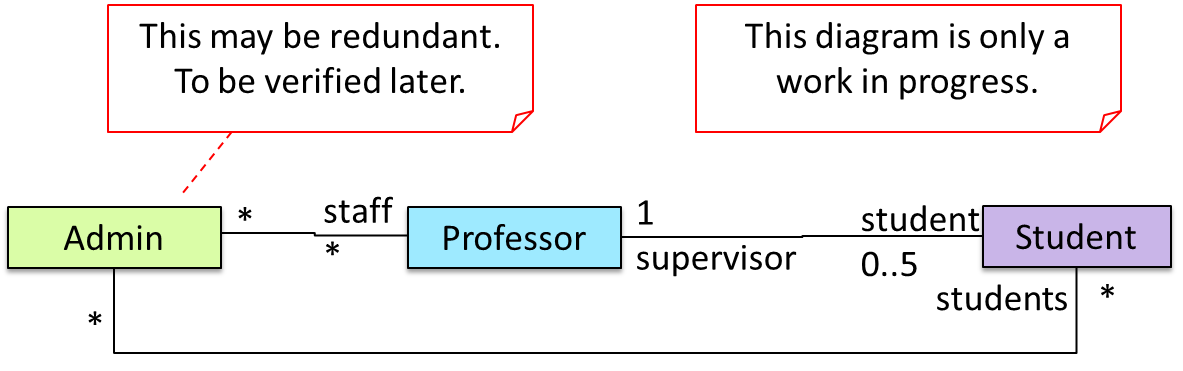
In the diagram below,
- Each student must be supervised by exactly one professor. i.e. There cannot be a student who doesn't have a supervisor or has multiple supervisors.
- A professor cannot supervise more than 5 students but can have no students to supervise.
- An admin can handle any number of professors and any number of students, including none.
- A professor/student can be handled by any number of admins, including none.
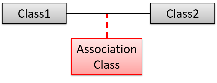
What
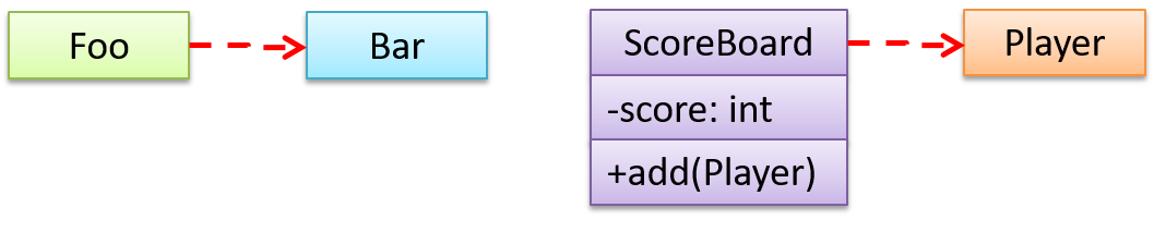
An association can be shown as an attribute instead of a line.
Association multiplicities and the default value too can be shown as part of the attribute using the following notation. Both are optional.
name: type [multiplicity] = default value
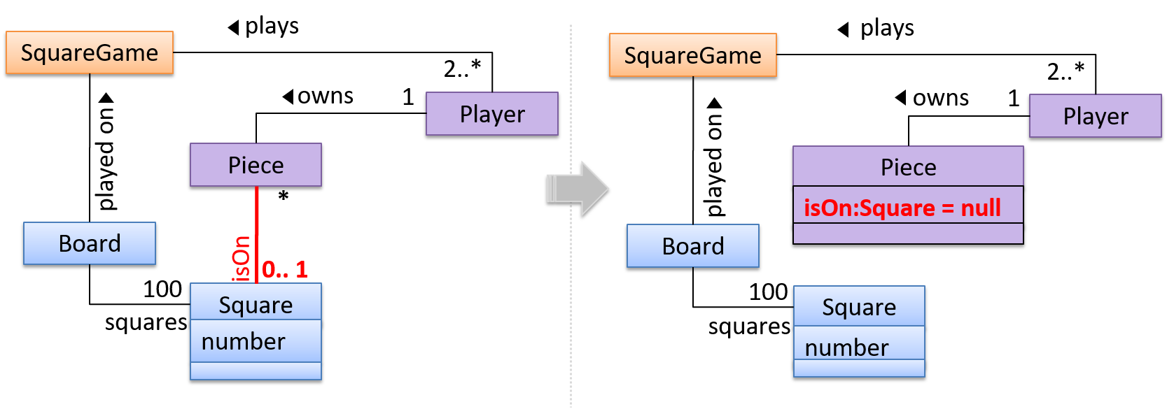
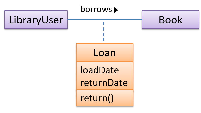
The diagram below depicts a multi-player Square Game being played on a board comprising of 100 squares. Each of the squares may be occupied with any number of pieces, each belonging to a certain player.
A Piece may or may not be on a Square. Note how that association can be replaced by an isOn attribute of the Piece class. The isOn attribute can either be null or hold a reference to a Square object, matching the 0..1 multiplicity of the association it replaces. The default value is null.
The association that a Board has 100 Squares can be shown in either of these two ways:
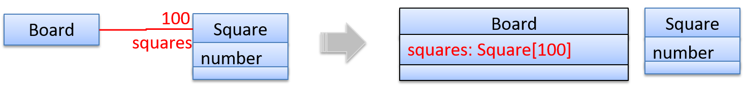
Show each association as either an attribute or a line but not both. A line is preferred is it is easier to spot.

What
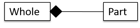
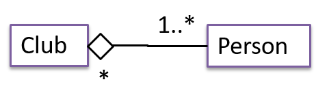
UML uses a hollow diamond is used to indicate an aggregation.
Notation:
Example:
Aggregation vs Composition
The distinction between composition (◆) and aggregation (◇) is rather blurred. Martin Fowler’s famous book UML Distilled advocates omitting the aggregation symbol altogether because using it adds more confusion than clarity.
What
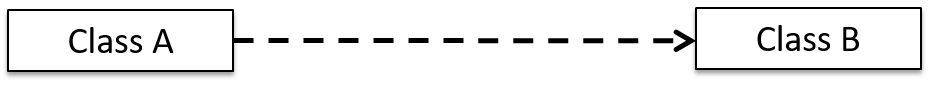
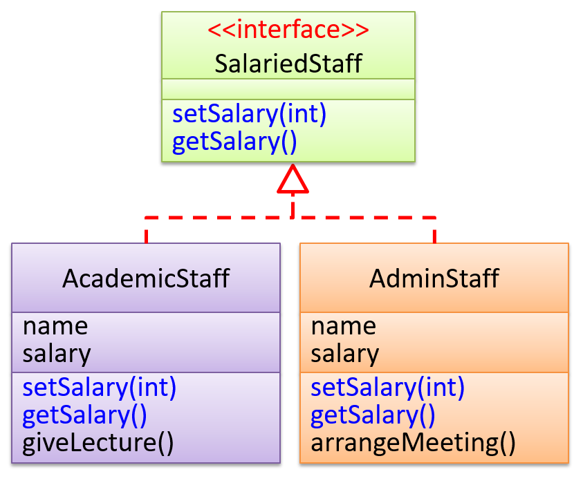
An interface is shown similar to a class with an additional keyword <<interface>>. When a class implements an interface, it is shown similar to class inheritance except a dashed line is used instead of a solid line.
The AcademicStaff and the AdminStaff classes implement the SalariedStaff interface.
Introduction
A UML sequence diagram captures the interactions between multiple objects for a given scenario.
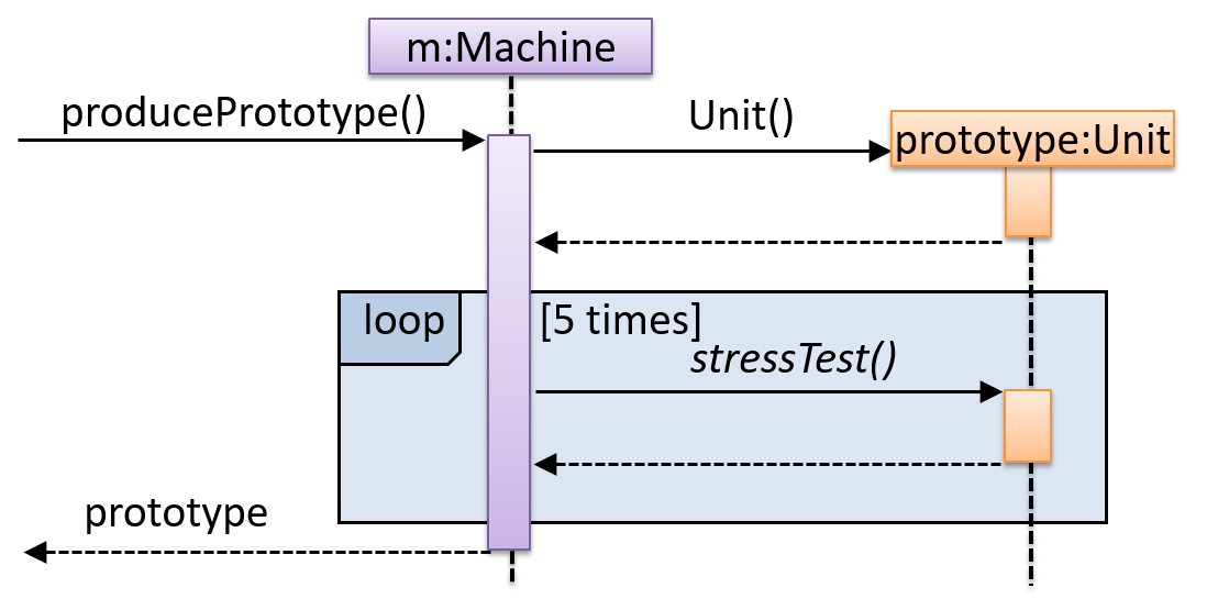
Consider the code below.
class Machine {

    Unit producePrototype() {
        Unit prototype = new Unit();
        for (int i = 0; i < 5; i++) {
            prototype.stressTest();
        }
        return prototype;
    }
}

class Unit {

    public void stressTest() {

    }
}
Here is the sequence diagram to model the interactions for the method call producePrototype() on a Machine object.
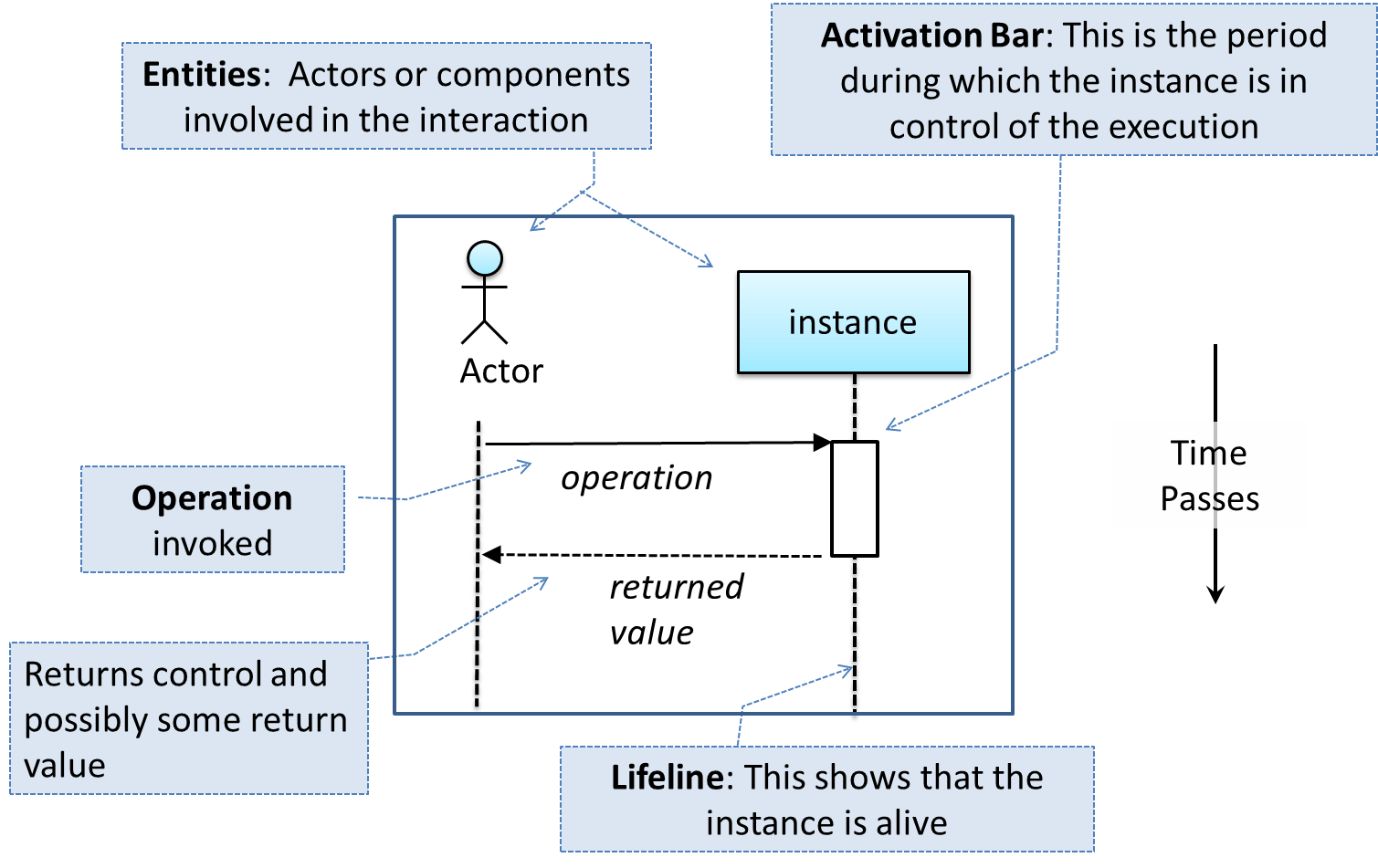
Basic
Notation:
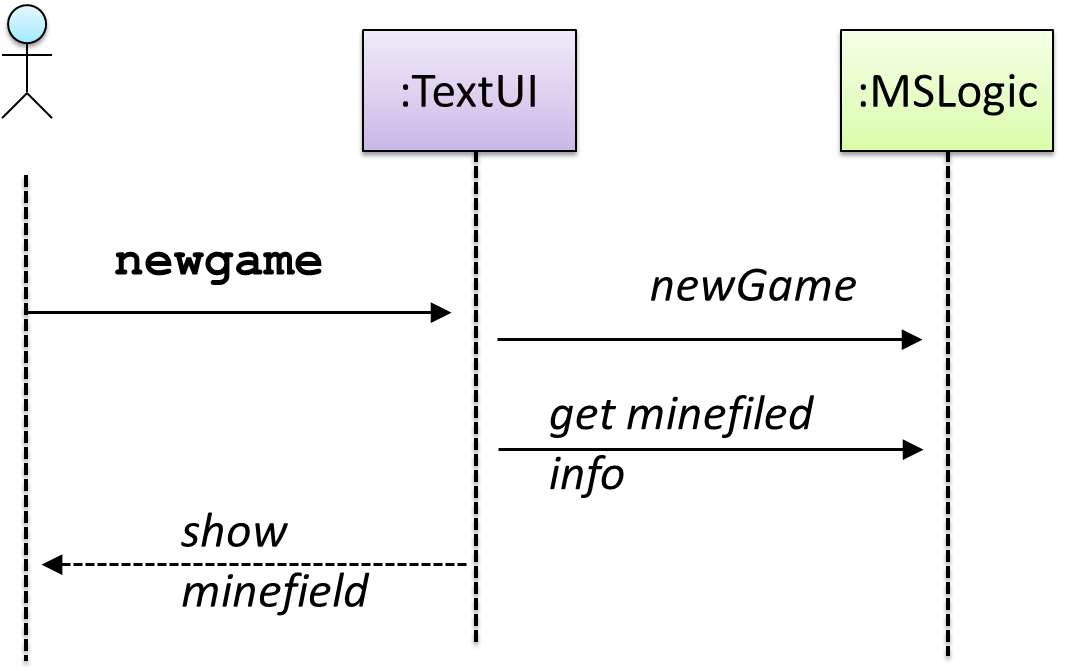
This sequence diagram shows some interactions between a human user and the Text UI of a
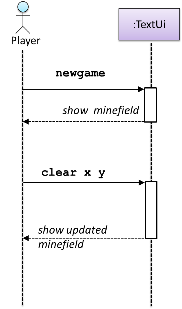
The player runs the newgame action on the TextUi object which results in the TextUi showing the minefield to the player. Then, the player runs the clear x y command; in response,
the TextUi object shows the updated minefield.
The :TextUi in the above example denotes an unnamed instance of the class TextUi. If there were two instances of TextUi in the diagram, they can be distinguished by naming them e.g. TextUi1:TextUi and TextUi2:TextUi.
Arrows representing method calls should be solid arrows while those representing method returns should be dashed arrows.
Note that unlike in object diagrams, the class/object name is not underlined in sequence diagrams.
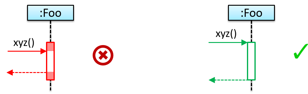
[Common notation error] Activation bar too long: The activation bar of a method cannot start before the method call arrives and a method cannot remain active after the method had returned. In the two sequence diagrams below, the one on the left commits this error because the activation bar starts before the method Foo#xyz() is called and remains active after the method returns.
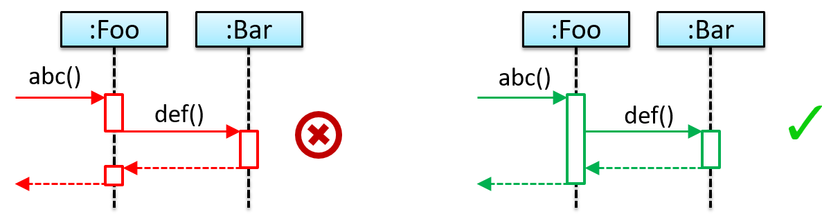
[Common notation error] Broken activation bar: The activation bar should remain unbroken from the point the method is called until the method returns. In the two sequence diagrams below, the one on the left commits this error because the activation bar for the method Foo#abc() is not contiguous, but appears as two pieces instead.
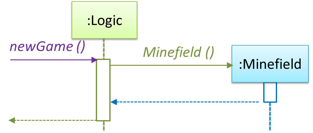
Object Creation
Notation:
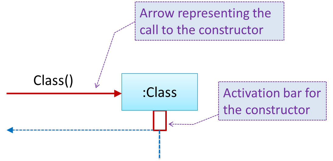
- The arrow that represents the constructor arrives at the side of the box representing the instance.
- The activation bar represents the period the constructor is active.
The Logic object creates a Minefield object.
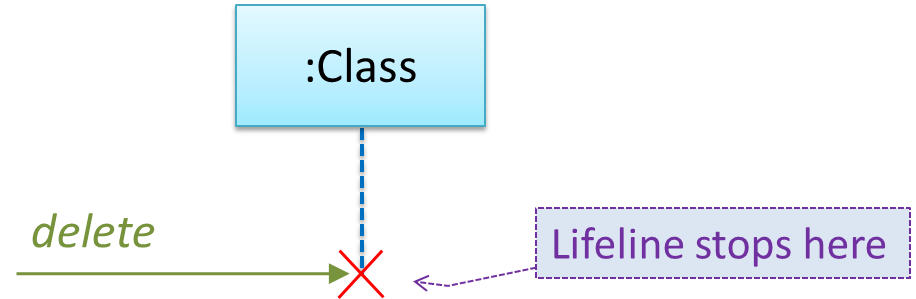
Object Deletion
UML uses an X at the end of the lifeline of an object to show it's deletion.
Although object deletion is not that important in languages such as Java that support automatic memory management, you can still show object deletion in UML diagrams to indicate the point at which the object ceases to be used.
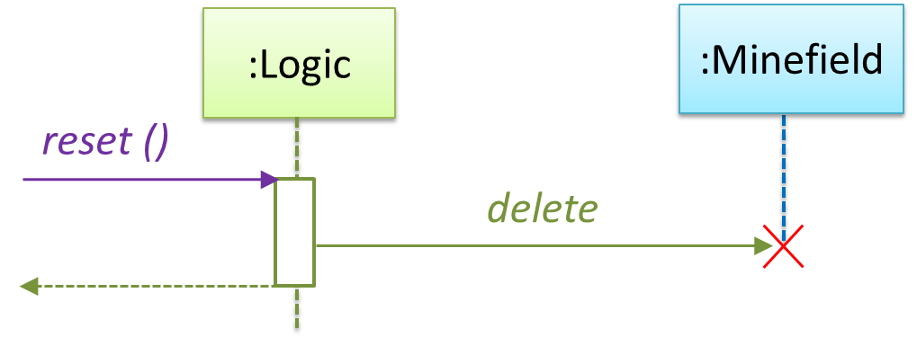
Notation:
Note how the diagrams shows the deletion of the Minefield object
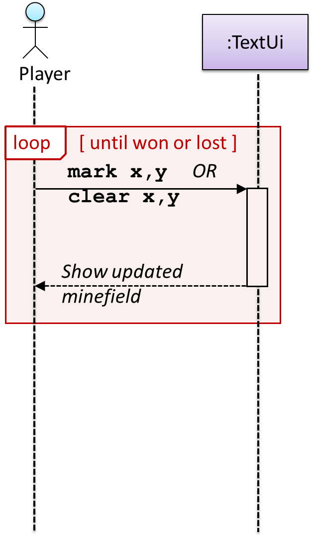
Loops
Notation:
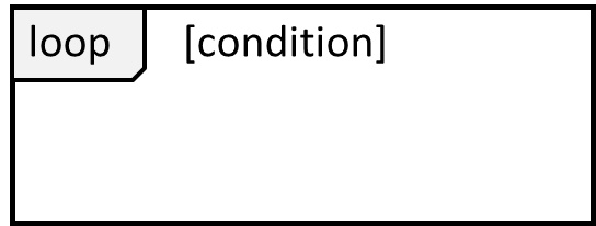
The Player calls the mark x,y command or clear x y command repeatedly until the game is won or lost.
Self Invocation
UML can show a method of an object calling another of its own methods.
Notation:
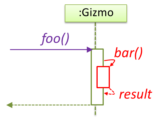
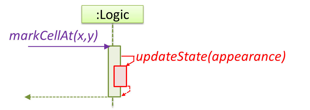
The markCellAt(...) method of a Logic object is calling its own updateState(...) method.
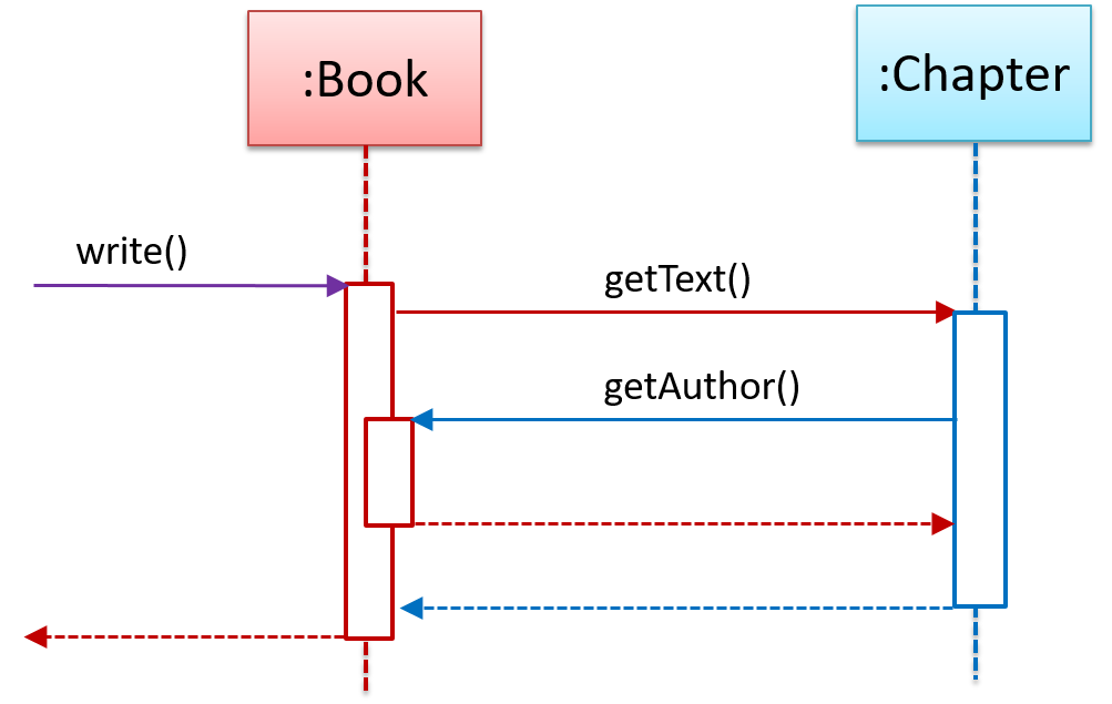
In this variation, the Book#write() method is calling the Chapter#getText() method which in turn does a call back by calling the getAuthor() method of the calling object.
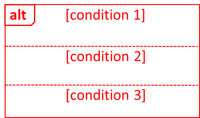
Alternative Paths
UML uses alt frames to indicate alternative paths.
Notation:
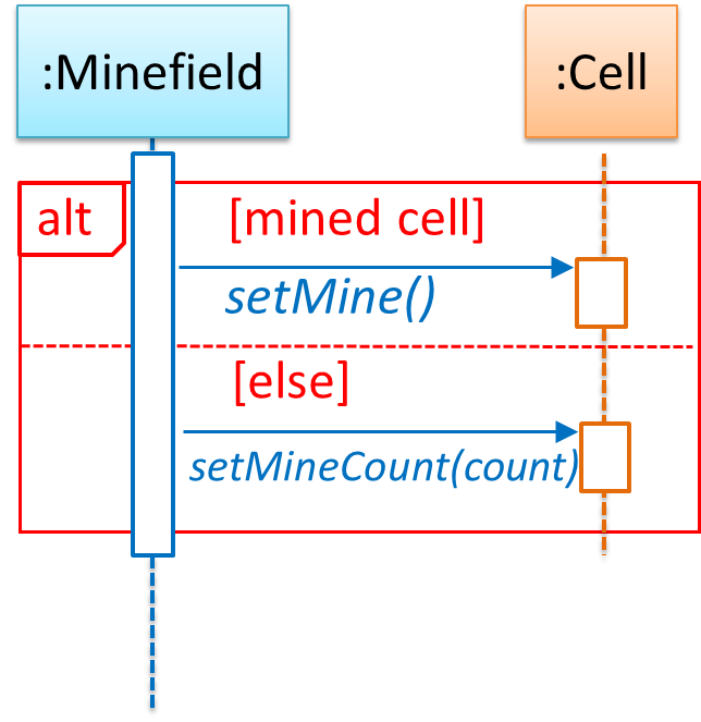
Minefield calls the Cell#setMine if the cell is supposed to be a mined cell, and calls the Cell:setMineCount(...) method otherwise.
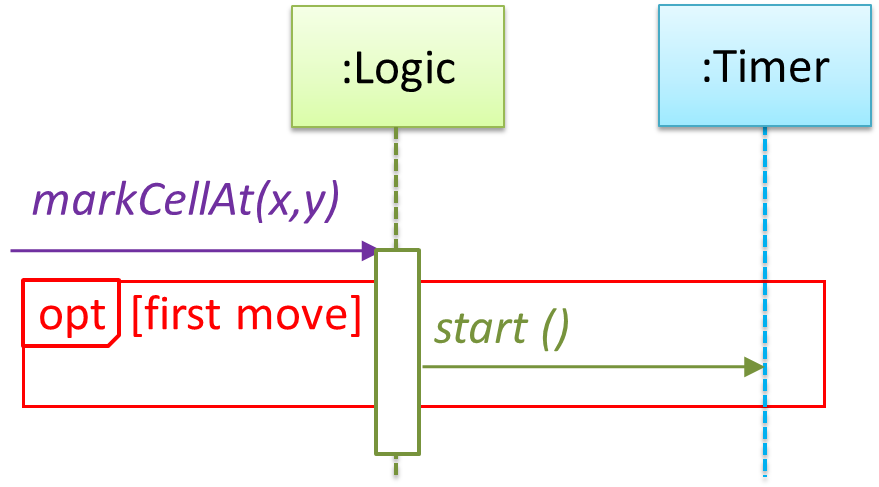
Optional Paths
UML uses opt frames to indicate optional paths.
Notation:

Logic#markCellAt(...) calls Timer#start() only if it is the first move of the player.
Parallel Paths
UML uses par frames to indicate parallel paths.
Notation:
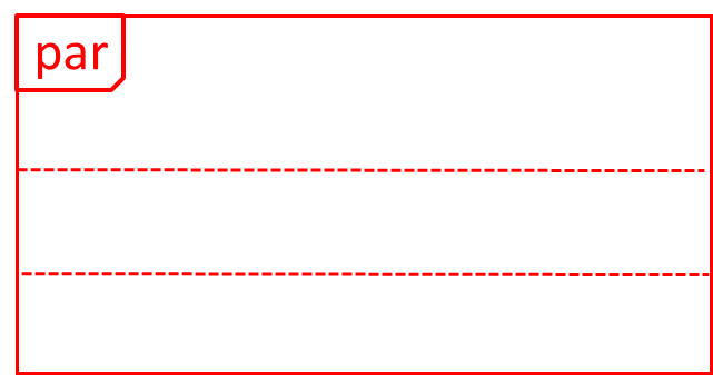
Logic is calling methods CloudServer#poll() and LocalServer#poll() in parallel.
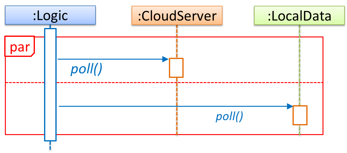
If you show parallel paths in a sequence diagram, the corresponding Java implementation is likely to be multi-threaded because a normal Java program cannot do multiple things at the same time.
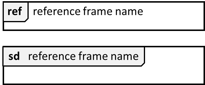
Reference Frames
UML uses ref frame to allow a segment of the interaction to be omitted and shown as a separate sequence diagram. Reference frames help us to break complicated sequence diagrams into multiple parts or simply to omit details we are not interested in showing.
Notation:
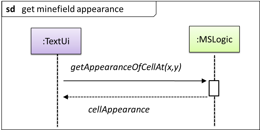
The details of the get minefield appearance interactions have been omitted from the diagram.
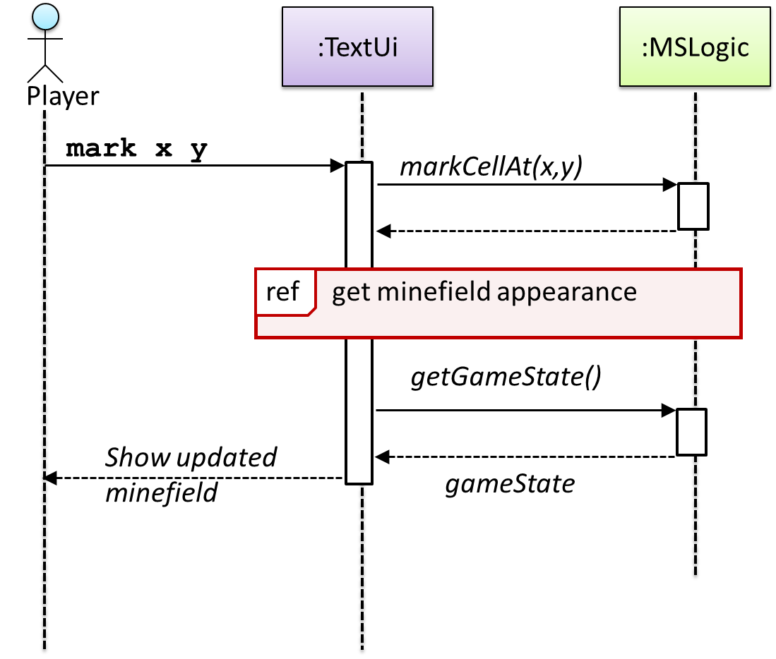
Those details are shown in a separate sequence diagram given below.
Minimal Notation
To reduce clutter, activation bars and return arrows may be omitted if they do not result in ambiguities or loss of information. Informal operation descriptions such as those given in the example below can be used, if more precise details are not required for the task at hand.
A minimal sequence diagram
Introduction
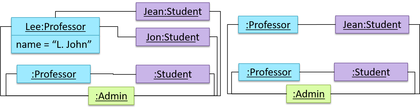
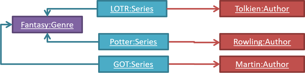
An object diagram shows an object structure at a given point of time.
An example object diagram:
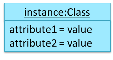
Objects
Notation:
Notes:
- The class name and object name e.g.
car1:Carare underlined. objectName:ClassNameis meant to say 'an instance ofClassNameidentified asobjectName'.- Unlike classes, there is no compartment for methods.
- Attributes compartment can be omitted if it is not relevant to the task at hand.
- Object name can be omitted too e.g.
:Carwhich is meant to say 'an unnamed instance of a Car object'.
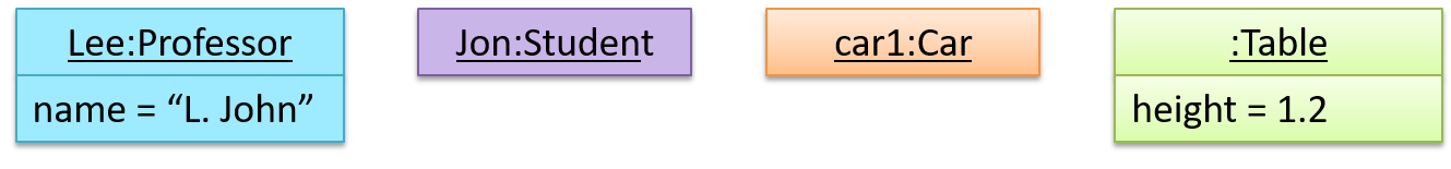
Some example objects:
What
Unified Modeling Language (UML) is a graphical notation to describe various aspects of a software system. UML is the brainchild of three software modeling specialists James Rumbaugh, Grady Booch and Ivar Jacobson (also known as the Three Amigos). Each of them has developed their own notation for modeling software systems before joining force to create a unified modeling language (hence, the term ‘Unified’ in UML). UML is currently the de facto modeling notation used in the software industry.
An example activity diagram:

[source:wikipeida]
Linear Paths
An activity diagram (AD) captures an activity of actions and control flows that makes up the activity.
- An action is a single step in an activity. It is shown as a rectangle with rounded corners.
- A control flow shows the flow of control from one action to the next. It is shown by drawing a line with an arrow-head to show the direction of the flow.
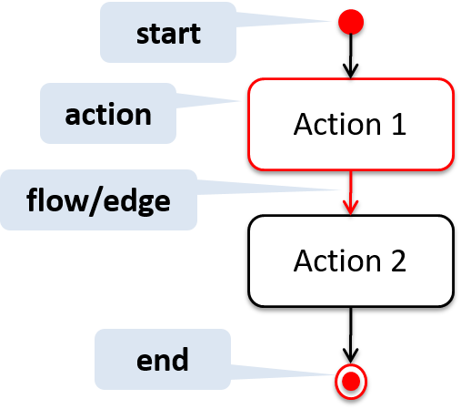
Note the slight difference between the start node and the end node which represent the start and the end of the activity, respectively.
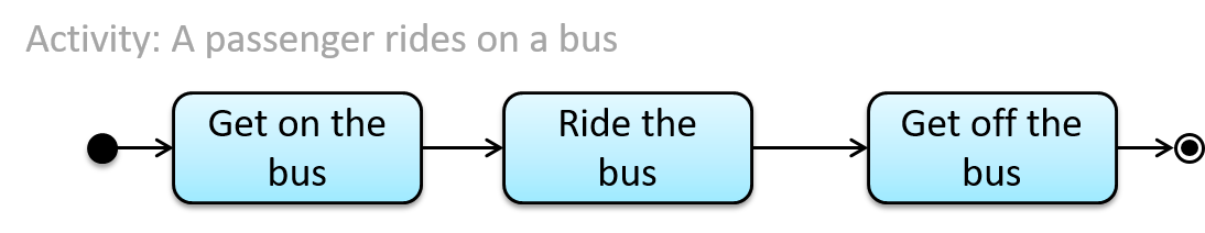
This activity diagram shows the action sequence of the activity a passenger rides the bus:
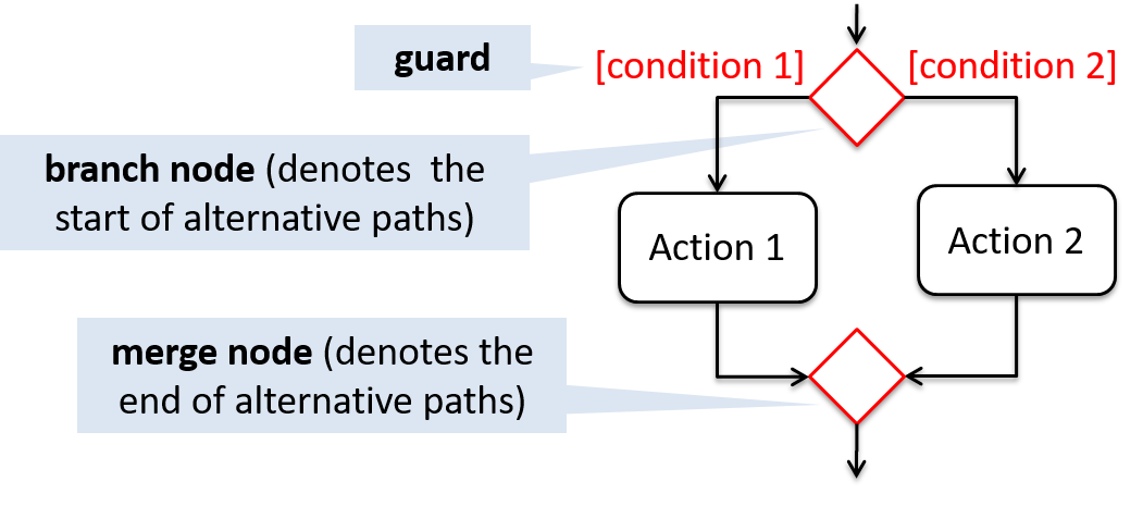
Alternate Paths
A branch node shows the start of alternate paths. Each control flow exiting a branch node has a guard condition : a boolean condition that should be true for execution to take that path. Only one of the guard condition can be true at any time.
A merge node shows the end of alternate paths.
Both branch nodes and merge nodes are diamond shapes. Guard conditions must be in square brackets.
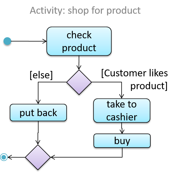
The AD below shows alternate paths involved in the workflow of the activity shop for product:
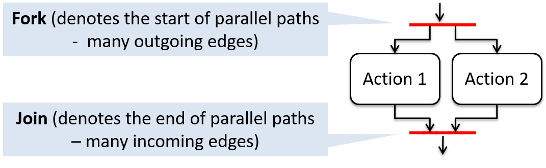
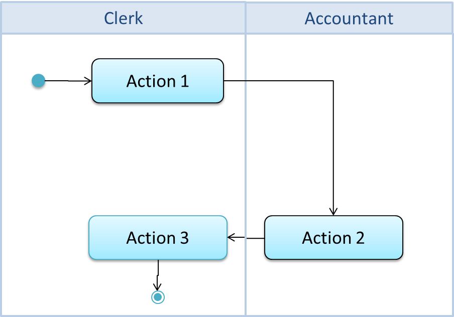
Parallel Paths
Fork nodes indicate the start of
Join nodes indicate the end of parallel paths.
Both have the same notation: a bar.
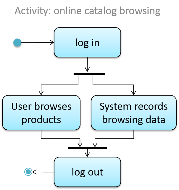
In a
In this activity diagram (from an online shop website) the actions User browsers products and System records browsing data happen in parallel. Both of them need to finish before the log out action can take place.
Rakes
The rake notation is used to indicate that a part of the activity is given as a separate diagram.
Here is the AD for a game of ‘Snakes and Ladders’.
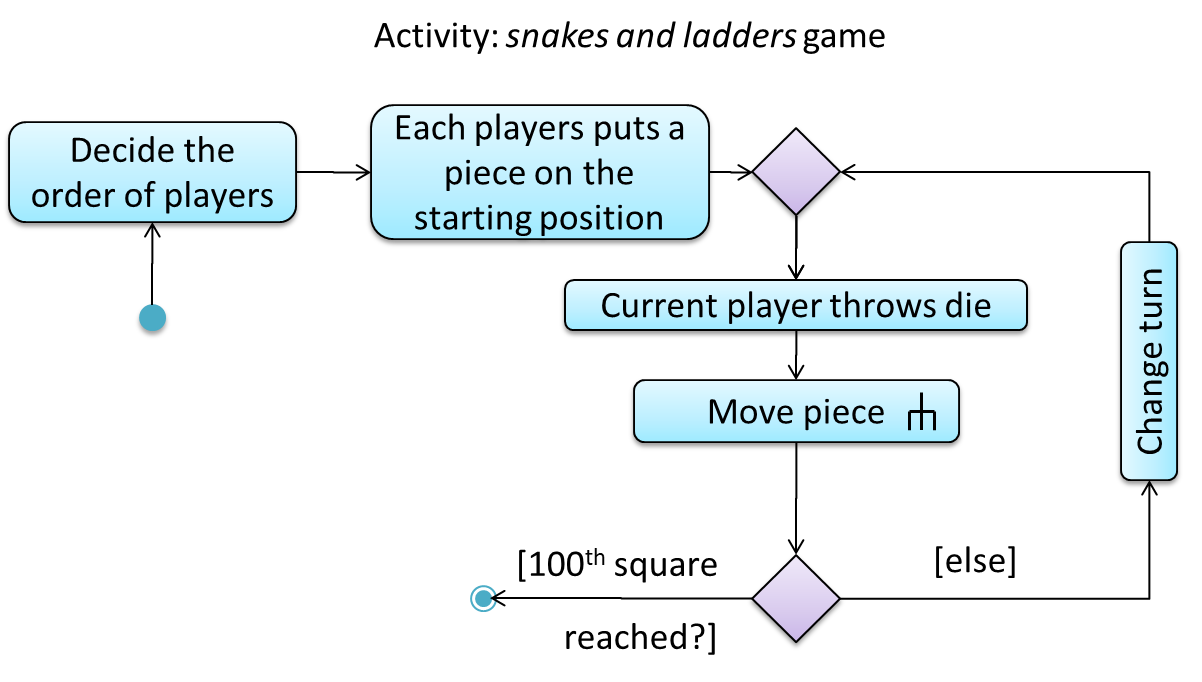
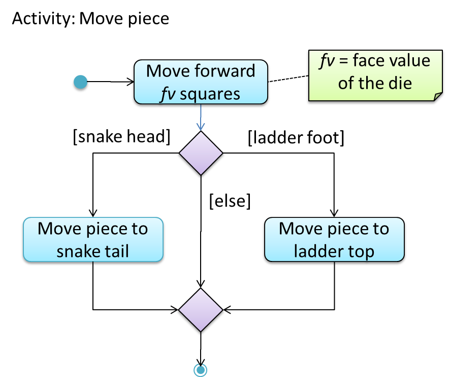
The rake symbol (in the Move piece action above) is used to show that the action is described in another subsidiary activity diagram elsewhere. That diagram is given below.
Object vs Class Diagrams
Compared to the notation for a class diagrams, object diagrams differ in the following ways:
- Shows objects instead of classes:
- Instance name may be shown
- There is a
:before the class name - Instance and class names are underlined
- Methods are omitted
- Multiplicities are omitted
Furthermore, multiple object diagrams can correspond to a single class diagram.
Both object diagrams are derived from the same class diagram shown earlier. In other words, each of these object diagrams shows ‘an instance of’ the same class diagram.